thread-locking insert for Z-stop screw

The place to discuss your hardware and software/firmware modifications...
nelsond6
Posts: 16
Joined: Wed Jan 07, 2015 9:36 pm

Re: thread-locking insert for Z-stop screw

Post by nelsond6 » Sat Mar 07, 2015 11:13 pm

sthone wrote:Oh yeah... I have a V4 I forgot I don't have to mess with the z-stop anymore :P (I might just do it to do it now though)

-Steve
Steve, I don't understand why having a V4 stops you from having to mess with the z-stop. Care to explain?

thanks,

-Dan

User avatar
sthone
Posts: 897
Joined: Tue Jul 08, 2014 8:25 pm
Location: Connecticut
Contact:

Re: thread-locking insert for Z-stop screw

Post by sthone » Sun Mar 08, 2015 3:00 am

nelsond6 wrote: Steve, I don't understand why having a V4 stops you from having to mess with the z-stop. Care to explain?

thanks,

-Dan
I haven't done this yet but, with the V4 you can easily adjust the height of the actual hot end right in the mount so in in theory you should be able to home the z axis, loosen the screw holding the hot end, and just lower the hot end until it kisses the feeler gauge and re-tighten the mounting screw and that should be the perfect z height.

-Steve
____________________________________________________
See my projects at https://www.theneverendingprojectslist.com

wmgeorge
Posts: 200
Joined: Thu Jun 18, 2015 1:09 am

Re: thread-locking insert for Z-stop screw

Post by wmgeorge » Sat Oct 10, 2015 1:52 pm

I just got my M2 and was in disbelief at the arrangement to adjust the Z stop. So I have been reading this with great interest. What I was planning was use the present M4 tapped hole and mount a thumb screw as suggested and with the knob under the plate. Between the knob and the plate slip a spring, weight to be determined by trial and error :o over the screw part. The spring applying pressure should keep it from turning on its own once set. After all that's the way carburetor screws for idle adjustment are locked from turning. :D

Edit McMaster Carr the longest M4 thumbscrew they stock is only 20 mm long, not enough to keep your hand away from the bottom plate. Might be using a allen head bolt once again threaded from the bottom up.
Retired Master Electrician, Commercial HVAC/R,CNC Router

Kulturfolger
Posts: 50
Joined: Thu Jul 30, 2015 8:56 pm

Re: thread-locking insert for Z-stop screw

Post by Kulturfolger » Sat Oct 10, 2015 4:42 pm

How about leaving the z-stop untouched and adjusting the z-height by software? It may be a wise choice to move the endstop to the bottom. I placed two springs around the shafts, when the z-stage goes into free fall the springs prevent the "smack" onto the z-stepper. Now I could imagine the z-endstop is placed on the low end. The z-stepper can easily work against the springs hitting the z-endstop. From there its defined where the "software" z-stop really is. There is no need to touch the z-stop anymore, the rest is done by the firmware.

I use this on other printers where the x-carriage is moving up and down. The z-stop is all the way upwards and the real zero position is calculated within the software. This way a broken z-stop never leads to a crash into the printbed.

Ingo
Feel free to correct my mistakes. English is not my native language.

wmgeorge
Posts: 200
Joined: Thu Jun 18, 2015 1:09 am

Re: thread-locking insert for Z-stop screw

Post by wmgeorge » Sat Oct 10, 2015 5:16 pm

Kulturfolger wrote:How about leaving the z-stop untouched and adjusting the z-height by software? It may be a wise choice to move the endstop to the bottom. I placed two springs around the shafts, when the z-stage goes into free fall the springs prevent the "smack" onto the z-stepper. Now I could imagine the z-endstop is placed on the low end. The z-stepper can easily work against the springs hitting the z-endstop. From there its defined where the "software" z-stop really is. There is no need to touch the z-stop anymore, the rest is done by the firmware.

I use this on other printers where the x-carriage is moving up and down. The z-stop is all the way upwards and the real zero position is calculated within the software. This way a broken z-stop never leads to a crash into the printbed.
Ingo

The Z stop is a hard setting for the Homing process. Can not be in software. But I believe the Z offset is already in S3D and other software slicers.
Retired Master Electrician, Commercial HVAC/R,CNC Router

Kulturfolger
Posts: 50
Joined: Thu Jul 30, 2015 8:56 pm

Re: thread-locking insert for Z-stop screw

Post by Kulturfolger » Sun Oct 11, 2015 8:00 pm

The command G28 within the "starting script" makes the printer home to zero on all axis. The last command in the default "starting script" is "G1 X180 Z0.25" which lowers the printbed from zero to 0.25mm.

When Z is not in the exact position where I want it to be, I just use the knob and turn it to dial in the right position. Keeping in mind that 200 full steps = one full turn = 8mm height travel this results in 0,04 mm per "tick". With the stepper turned on there is a tick every full step.

For the last print I taped capton tape on the glass. The print head was too close to the surface. I had to turn the knob three "ticks" to get to the correct distance. That means I've moved the table 3 times 0.04mm down. I changed the Z0.25 to Z0,37. The next print will start at the correct height, without touching the knob.

PS: Sorry for my english, I hope everyone understands what I mean.

Ingo
Feel free to correct my mistakes. English is not my native language.

User avatar
ednisley
Posts: 1188
Joined: Fri Apr 11, 2014 5:34 pm
Location: Halfway up the Hudson
Contact:

Re: thread-locking insert for Z-stop screw

Post by ednisley » Sun Oct 11, 2015 10:28 pm

Kulturfolger wrote:I changed the Z0.25 to Z0,37. The next print will start at the correct height
That's the next print from that G-Code file, because the slicer doesn't know about that change. You must manually change all subsequent models to incorporate that offset.

In any event, changing the first G1 command after the G28 command won't affect the other layers in that file. For a model sliced with 0.25 mm layer thickness, manually changing the G1 for the first layer to Z=0.37 will squish the second layer: the platform will move only 0.50 - 0.37 = 0.13 mm between the first and second layers. All the layers after that will be 0.25 mm apart.

Instead, use a G92 command to force the current Z-axis position to have a specific value. In your case, you'd use G92 Z-0.12 to tell the printer that the platform is 0.12 mm too close to the nozzle. Then all of the G1 Z... commands will move to the correct location relative to the platform's actual position.

You can put the G92 command in the start G-Code that the slicer prepends to the outgoing G-Code file, after which all subsequent sliced models will Just Work with the new offset.

A walkthrough of the start G-Code I'm using may show how that works:
http://softsolder.com/2015/03/31/makerg ... -whatever/

You can also put the initial origin value into the G28 command, rather than a separate G92 command.

wmgeorge
Posts: 200
Joined: Thu Jun 18, 2015 1:09 am

Re: thread-locking insert for Z-stop screw

Post by wmgeorge » Sun Oct 11, 2015 10:56 pm

I had assumed we were taking about the Z Switch Mechanical switch stop and its adjustment? I have mine already switched over the thumb screw adjustment from the bottom side with a compression spring acting as a locking device. Any Z offset from that hard stop can be made either in the software or the knob on top of the Z screw.
Having said that I did learn something new about changing the offset in the software that can be permanent. Thanks for posting Ed
Retired Master Electrician, Commercial HVAC/R,CNC Router

User avatar
ednisley
Posts: 1188
Joined: Fri Apr 11, 2014 5:34 pm
Location: Halfway up the Hudson
Contact:

Re: thread-locking insert for Z-stop screw

Post by ednisley » Mon Oct 12, 2015 1:51 am

wmgeorge wrote:the Z Switch Mechanical switch stop and its adjustment
Point is, if you set the offset using a G92 Z... in the start G-Code, then you don't need any mechanical adjustment, at least after you set the switch to trip within a few millimeters of the desired position.

In fact, I moved that switch to the X-axis gantry. It trips when the platform is about 2 mm higher than the nozzle (so, obviously, the startup code must move the nozzle off the platform before homing Z!) and I use G92 to set the Z=0 position exactly at the nozzle tip. No mechanical adjustments at all: no locking screws, no thumbscrews, nothing!

As long as the nozzle remains at the same offset from the switch trip position (which it will, if you don't remove the hot end), the G92 offset remains constant. I can (and have!) re-aligned the platform without doing anything else, because the switch detects the glass when it's at the same position relative to the nozzle.

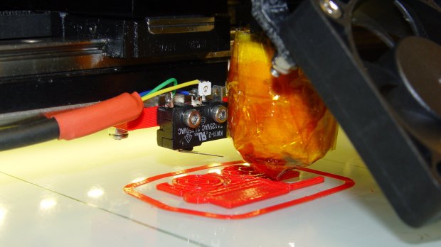
The first pass with the V3 hot end had the switch on a printed block:
http://softsolder.com/2013/10/14/makerg ... in-switch/

Image

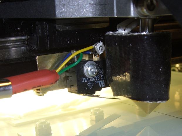
The V4 hot end called for an actual metal bracket:
http://softsolder.com/2015/03/10/makerg ... is-switch/

Image

Measure the offset once, set the G92 Z value, done!

Simple, easy, cheap. Oddly, nobody else likes it... [sigh]

jsc
Posts: 1864
Joined: Thu Apr 10, 2014 4:00 am

Re: thread-locking insert for Z-stop screw

Post by jsc » Mon Oct 12, 2015 3:25 am

I like it, Ed. It's very elegant. But I lack a parts bin stuffed with brass shims and machine tools to work it with.

Post Reply