Hey all,
I have seen many discussions on this forum regarding modifications to the MakerGear M2. I have done a few modifications to my printer and I think these modifications are key to the success of my printing.
Modifications have included MIC 6 aluminum plate with the use of PEI or Ultem, inductive sensor with the use of updated Marlin firmware to include mesh bed leveling or also known as auto bed leveling bilinear, and an LCD screen.
Here are the details and steps around the modifications, these will probably void the warranty on the printer and this is to be done at your own risk:
I have attached a PDF that has pics.
Model of Printer: MakerGear M2 Rev. E
MIC 6 Plate and PEI:
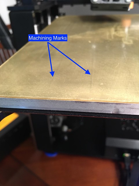
I ordered my MIC 6 plate (8in x 10in x 1/4in thick) from a local metal supply company costing about $50. I had the plate glass bead blasted to get a rough surface for adhesion (note: the MIC 6 plate is needed for the inductive sensor discussed later.) Using 3M 468MP adhesive transfer tape $23 to apply the PEI sheet $30 that has been cut down to fit the plate. (Note: The PEI sheet is .04in thick and is machinable, so I had a friend who works at a machine shop mill the plate with the adhesive and the PEI to make the surface as flat as possible. This is probably an extreme approach to get a flat surface.)
 Pasted Graphic 1
 by
Marc Vogel, on Flickr
3M 468MP Adhesive Transfer Tape
https://www.amazon.com/gp/product/B007Y ... UTF8&psc=1
PEI or Ultem
https://www.zoro.com/ultem-sheet-stck-1 ... /G1023897/
Inductive sensor and Marlin upgrade:
Before the wiring for the sensor is started, there needs to be a mount for the sensor. I have revamped the filament drive part to include a mounting point for the sensor. The stl can be downloaded from Thingiverse here:
http://www.thingiverse.com/thing:2013353

Ordered inductive sensors from Amazon $6 (1st sensor didn’t work so ordered a 2nd and it worked) and also
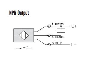
Automationdirect.com $22. Both sensors work well and to test them use a 9V battery apply brown lead to positive and blue lead to negative and place the sensor close to a metal object, it should light up.
 Pasted Graphic 2
 by
Marc Vogel, on Flickr
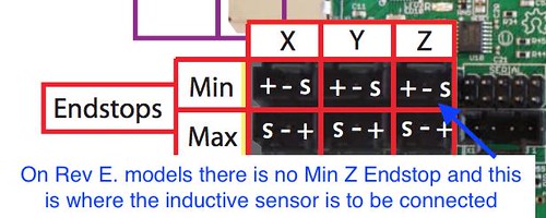
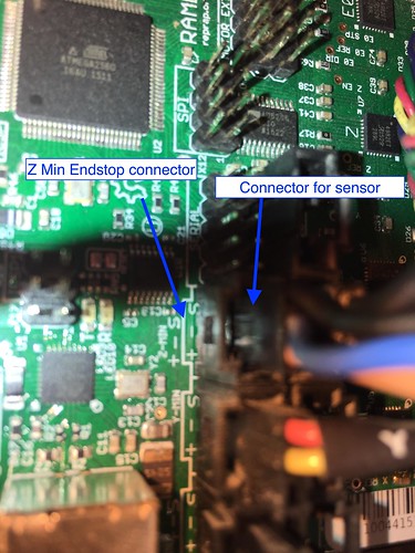
Next wire the sensor to a 3 terminal connector (I used a Dupont female connector) following the schematic above and the Rambo board schematic below.
 Pasted Graphic 3
 by
Marc Vogel, on Flickr
End results should look like the following:
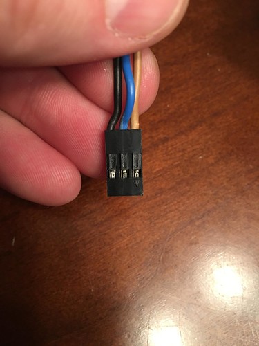 Pasted Graphic 4
 by
Marc Vogel, on Flickr
 Pasted Graphic 5
 by
Marc Vogel, on Flickr
Inductive Sensors
https://www.amazon.com/gp/product/B008F ... UTF8&psc=1
https://www.automationdirect.com/adc/Sh ... /AK1-AN-2A
LCD Screen:
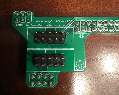
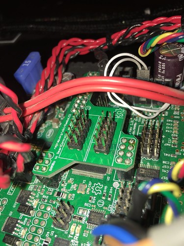
I used the RepRapDiscount Smart Controller from Ultimachine.com $50 be sure to get the RAMBo one. Installing the LCD was pretty straight forward.
 Pasted Graphic 6
 by
Marc Vogel, on Flickr
 Pasted Graphic 7
 by
Marc Vogel, on Flickr
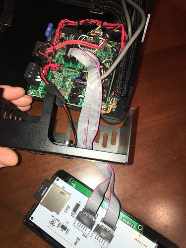
I removed the SD card because the LCD comes with one and used the opening to route the cables. There are many cases for the LCD on Thingiverse so I am not going to go over that.
 Pasted Graphic 8
 by
Marc Vogel, on Flickr
LCD Screen
https://ultimachine.com/collections/ele ... apdiscount
Firmware Update:
This part was a little complicated. I have some coding experience so that helped work through all of this. I am using Arduino 1.6.12 with the RAMBo plugin found here
https://github.com/ultimachine/RAMBo/tr ... uino_1.x.x
First I compared the MakerGear firmware with Marlin 1.1.0-RC8 - 6 Dec 2016. I tried to document this as best as I could. Still work in progress. Here are the changes to the firmware that I have made to make it work.
Changes in Configuration.h
#define CUSTOM_MACHINE_NAME "M2E" // Marc
#define POWER_SUPPLY 1 // Marc
#define TEMP_SENSOR_BED 1 // Marc
#define TEMP_RESIDENCY_TIME 5 // (seconds) // Marc
#define TEMP_HYSTERESIS 4 // (degC) range of +/- temperatures considered "close" to the target one // Marc
#define TEMP_WINDOW 2 // (degC) Window around target to start the residency timer x degC early. // Marc
#define TEMP_BED_RESIDENCY_TIME 5 // (seconds) // Marc
#define HEATER_0_MAXTEMP 305 // Marc
//#define DEFAULT_Kp 22.2 // Marc commented out
//#define DEFAULT_Ki 1.08 // Marc commented out
//#define DEFAULT_Kd 114 // Marc commented out
#define DEFAULT_Kp 25.89 // Marc
#define DEFAULT_Ki 1.94 // Marc
#define DEFAULT_Kd 86.53 // Marc
#define EXTRUDE_MAXLENGTH (X_MAX_LENGTH+Y_MAX_LENGTH) // Marc
#define USE_XMIN_PLUG // Marc
#define USE_ZMIN_PLUG // Marc z-probe
#ifdef ENDSTOPPULLUPS // Marc
#define ENDSTOPPULLUP_XMAX // Marc
#define ENDSTOPPULLUP_YMAX // Marc
#define ENDSTOPPULLUP_ZMAX // Marc
#define ENDSTOPPULLUP_XMIN // Marc
#define ENDSTOPPULLUP_YMIN // Marc
#define ENDSTOPPULLUP_ZMIN // Marc
#endif // Marc
#define X_MIN_ENDSTOP_INVERTING true // set to true to invert the logic of the endstop. // Marc
#define Y_MIN_ENDSTOP_INVERTING true // set to true to invert the logic of the endstop. // Marc
#define Z_MIN_ENDSTOP_INVERTING true // set to true to invert the logic of the endstop. // Marc
#define X_MAX_ENDSTOP_INVERTING true // set to true to invert the logic of the endstop. // Marc
#define Y_MAX_ENDSTOP_INVERTING true // set to true to invert the logic of the endstop. // Marc
#define Z_MAX_ENDSTOP_INVERTING true // set to true to invert the logic of the endstop. // Marc
#define DEFAULT_AXIS_STEPS_PER_UNIT { 88.88, 88.88, 1007.7, 471.5 } // default steps per unit for Ultimaker //v000 9/24/2015 // Marc
#define DEFAULT_MAX_FEEDRATE { 200, 200, 25, 25 } // (mm/sec) //changed as per Scott's request - 1/12/2016 Josh // Marc
#define DEFAULT_MAX_ACCELERATION { 900, 1000, 30, 2000 } // X, Y, Z, E maximum start speed for accelerated moves. E default values are good for Skeinforge 40+, for older versions raise them a lot. -- Changed these from (9000,9000,100,10000) to (900,1000,30,2000) as per Scott's requests - 1/12/2016 Josh // Marc
#define DEFAULT_ACCELERATION 2000 // X, Y, Z and E acceleration for printing moves //changed as per Scott's request - 1/12/2016 Josh // Marc
#define DEFAULT_XJERK 4.0 // (mm/sec) //changed this from 20 to 4, as per Scott's request - 1/12/2016 Josh // Marc
#define DEFAULT_YJERK 4.0 // (mm/sec) //changed this from 20 to 4, as per Scott's request - 1/12/2016 Josh // Marc
#define DEFAULT_EJERK 1.0 // Marc
#define FIX_MOUNTED_PROBE // Marc
#define X_PROBE_OFFSET_FROM_EXTRUDER 35 // X offset
#define Y_PROBE_OFFSET_FROM_EXTRUDER 5 // Y offset
#define INVERT_X_DIR true // Marc
#define INVERT_Y_DIR false // Marc
#define Z_HOME_DIR 1 // Marc
#define min_software_endstops false // If true, axis won't move to coordinates less than HOME_POS. // Marc
#define max_software_endstops false // If true, axis won't move to coordinates greater than the defined lengths below. // Marc
#define X_MAX_POS 205 // Marc
#define Y_MAX_POS 255 // Marc
#define Z_MAX_POS 205 // Marc
#define Z_SAFE_HOMING // Marc
#define SDSUPPORT // Marc
#define REPRAP_DISCOUNT_SMART_CONTROLLER // Marc
Changes in Configuration_adv.h
#define CONTROLLERFAN_PIN 6 //Pin used for the fan to cool controller (-1 to disable) // Marc
#define BABYSTEPPING // Marc
#define FILAMENT_CHANGE_FEATURE // Enable filament exchange menu and M600 g-code (used for runout sensor too) // Marc
WARNINGS!!!!
I have not tested this with the Quick Start App. And doing all this could void the warranty on the printer!
I will add another post to show how to do the leveling adjustments. It is not hard, but the process can be a little confusing.
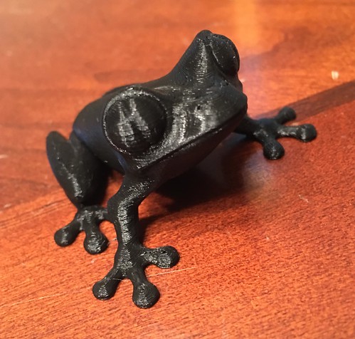
This is what my prints look like using simplify3d at .1mm layer height. Printing has never been easier.
~Marc