Almost up and running. I have my Z-probe acting as a Z-min stop but have not yet tried enabling the Z-probe capabilities in firmware. It's enough for me to post my solution. Note that this solution is for the dual extruder assembly
only, and requires either a metal bed surface (untested) or a Zebra plate (which has a copper layer inside. This is what I have, and has been tested).
I used the popular LJ12A3-4-Z/BY, because it was cheap and easy to come by, although the BZ is in some respects easier to work with. However, to make it completely compatible with the controller board's endstop switch connections, I needed to add some extra hardware anyway, so in the end I had to build a little circuit board for it and an extra component didn't make much difference.
I also decided not to run the device at 5V as in the original MakerGear instructions, but instead decided to drive it with the main 24V supply.
First is the fan duct. The best place to mount the Z probe is
between the fan and the rest of the extruder. The fan duct is very much in the way. However, the fan duct for the most part directs the air to the left and right, so the middle is largely empty. I made a few measurements and decided that with only a little modification, I could just punch an 11mm hole straight through the fan duct. The harder part was finding a place to put the nuts to hold it in place; one nut could go on the underside, but the other ended up having to be inside the fan duct, right behind the fan. Not ideal, but it works. I had to extend the fan duct outward by a few millimeters to prevent the nut from hitting the fan blade.
The resulting fan duct model is too big to post here, but I have placed in on my website at
http://opencircuitdesign.com/~tim/archi ... zprobe.zip
After printing the modified fan duct (I printed it in opaque black PETg; needs a significant amount of support, which S3D handled without issue),
insert the Z probe from the bottom, wires first, making sure the hex nut goes inside the fan duct and the wires go through the hex nut, because there's no other way to get the hex nut on (sorry about the black-on-black photo; you can barely see the hex nut in there).
- zprobe2a.jpg
- Threading the Z probe through the modifed fan duct
- (125.23 KiB) Downloaded 161 times
Once the Z probe is pushed into place, thread the hex nuts onto both ends, loosely.
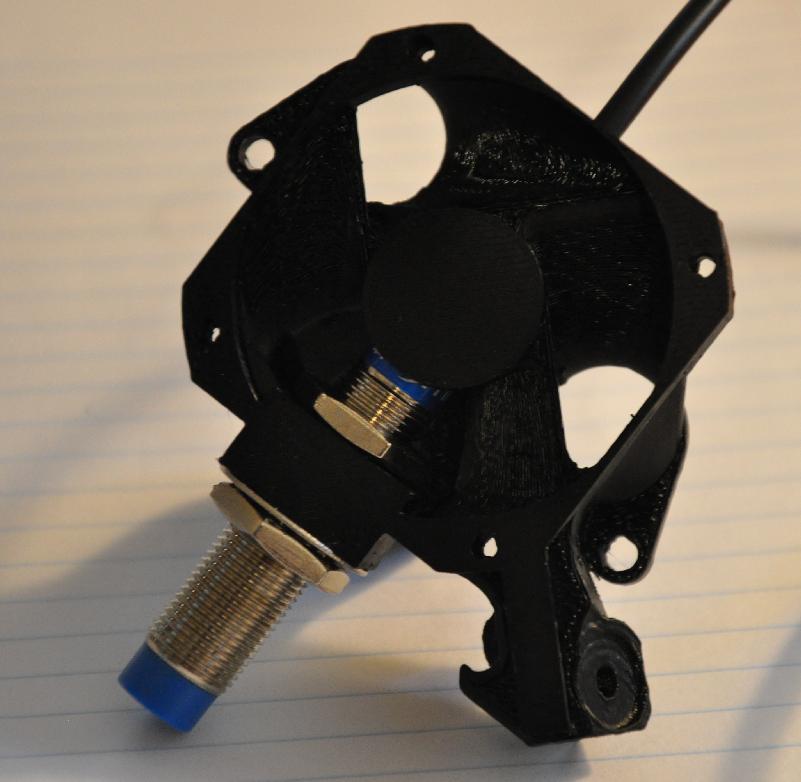
- Z probe installed in fan duct
- zprobe3a.jpg (111.4 KiB) Viewed 16174 times
Now bolt the fan duct back onto the extruder assembly.
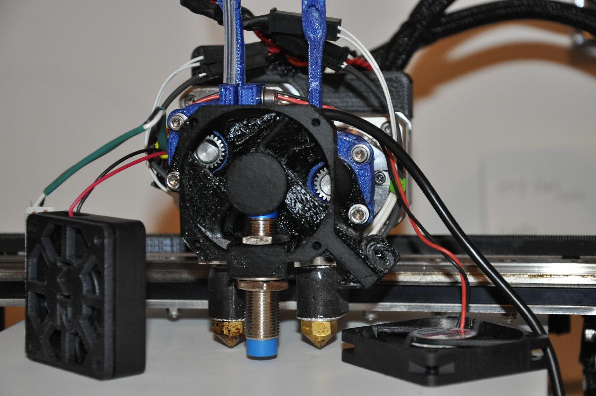
- Z probe and fan duct mounted and ready for height adjustment
- zprobe4a.jpg (178.81 KiB) Viewed 16174 times
Before putting the fan back on, adjust the height of the Z probe relative to the nozzles. This is best done by putting the bed into the correct position under the nozzle. Then connect the brown wire of the Z probe to the positive terminal of a 9V battery, and the blue wire to the negative terminal. If you move the Z probe up and down, it should light up when it gets close to the bed. Adjust it to the position where it is turned on, but any higher position will cause it to turn off. Tighten the hex nuts. Note that the LED on the Z probe is deeply buried in the fan duct, but it can be seen (barely) from above.
Once the Z probe has been tightened into position, put the fan back on, and the assembly is complete. The Z probe has a nice, flexible cable, so cable-tie that to the rest of the cable harness running to the controller board.

- Completed and installed Z probe
- zprobe5a.jpg (151.05 KiB) Viewed 16174 times
The following circuit diagram shows what circuitry needs to go between the Z probe and the Z-min endstop on the controller board. The two problems with the Z probe---namely, needing to run above 6V, and having a PNP configuration that shorts output to power, are solved with a 3904 NPN transistor with a voltage divider in front. The voltage divider drops the 24V output of the active Z probe down to 5V at the transistor base (the transistor can take 6V max). The NPN transistor then acts just like any of the other mechanical endstop switches: It's an open circuit (approximately) when the Z probe is inactive, and a closed circuit (approximately) when the Z probe is active. The NPN transistor outputs are then connected to the ZMIN endstop connector as shown, and it is a drop-in replacement. The only other connection is the brown wire for the Z probe, which needs to be wired into one of the 24V supplies on the controller board (I screwed mine into one of the power terminals, not necessarily the best method). The resistors in the circuit need not have the exact values shown, but should be in the 5-50 kilo-ohm range and have a ratio of 3.8 to 1 minimum, 4.3 to 1 maximum.

- Electronics to make the Z probe compatible with the contoller board endstop connectors
- zprobe_switch.png (20.79 KiB) Viewed 16174 times
I built the small circuit on a tiny piece of vectorboard I had lying around, and had to make another 3-position connector for the Z-min endstop. I removed the existing Z-min connector, moved the Z endstop switch up out of the way, and plugged the new connector into the Z-min. I tested with the manual gcode "M119", checking that it reports "zmin=0" normally, and "zmin=1" when I stick a screwdriver directly under the probe. Next step was to check that "zmin=1" when I carefully adjust the bed close to the nozzles. Next step was to do "home Z" from a far-away position and check that the movement stops when I put the screwdriver under the probe. Then I ran "home Z" on its own with the confidence that it would not crash the bed into the nozzle.
Firmware for the tramming is another matter, but this much gets you a Z probe that acts like a Z endstop switch close to the extruder nozzle.