Page 3 of 6
Re: Modified Ikea enclosure
Posted: Sat Feb 14, 2015 4:13 am
by msmollin
Here's mine, 90% of the way done. Everything is installed and working, though. Need to print out the holder for my webcam, mount the Pi (for octopi) to the wall as well, and do some wire management. Also, the LEDs while blue-tinted are nowhere near that blue in person. They're also remote controlled, which is both neat and fairly unnecessary at the same time!
Re: Modified Ikea enclosure
Posted: Sun Mar 22, 2015 4:19 pm
by atomholc
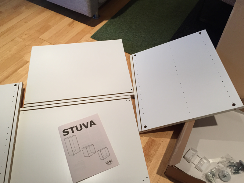
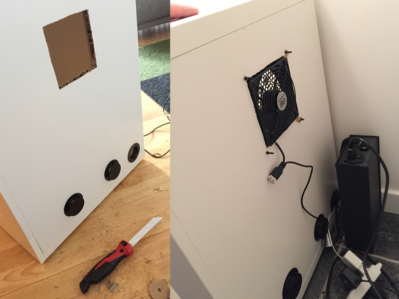
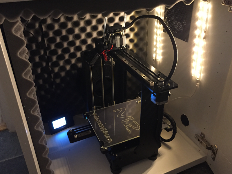
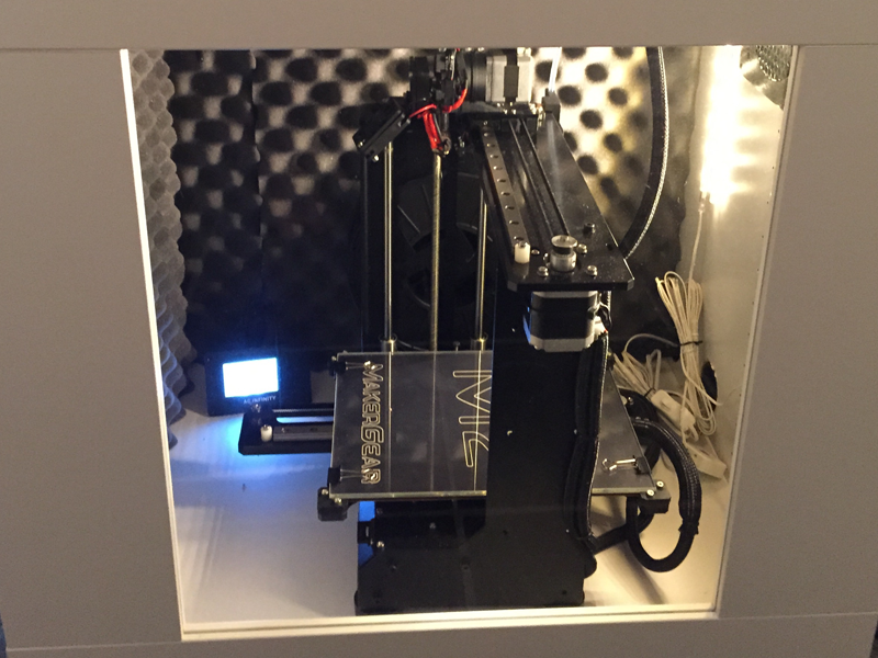
Hey Makers, first time posting here and I just starting getting into 3d design and printing this year. Thanks for all the tips and source links to build this. I just got mine up and running. It has been great for GREATLY reducing the noise and giving it a proper place to live inside my loft.
A few upgrades I am going to eventually add is a carbon filter for the exhaust fan, some additional sound proofing and a webcam to monitor the prints.
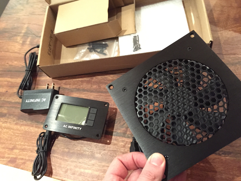
For the fan I went with this one
AC Infinity AIRPLATE T3
http://www.amazon.com/gp/product/B00QFW ... UTF8&psc=1
It is super quiet and the control panel is very intuitive to set. It works great to regulate the temperature.
Sound panels:
http://www.amazon.com/gp/product/B0002Z ... UTF8&psc=1
It would only recommend using this foam for the back and top panel. There isn't enough room for the machine to work if you put it on both sides. I am going to find a thinner lower profile foam for those areas.
I made a 2" inch cable plug incase anybody wants the source files:
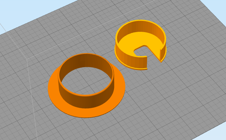 http://www.14113.net/3dprints/cableplug/sourcefiles.zip
Here is my setup:

Thanks!
Adam
Re: Modified Ikea enclosure
Posted: Sun Mar 22, 2015 7:09 pm
by pyronaught
The ceiling tiles used in offices are also sound deadening and might allow you so use them on all walls since they are much thinner. I built a sound muffling box for a dot matrix printer back in the 80s using those ceiling tiles and it seemed to work. Usually home improvement stores carry them.
Re: Modified Ikea enclosure
Posted: Mon Mar 23, 2015 4:50 am
by benavery
To those who have posted their temp-controlled fan setups, how are you finding them working. I upgraded from a 90 -> 120mm fan, but with the controller set at 31C (87F) after about 2 hours into a print (with a 70C bed heater) the fan just can't keep up, the fan is locked on, and temp started slowly rising toward 33C+
I do have the 120mm fan still running through a 90mm hole (with a duct/coupling I printed), so I could try cutting a bigger hole - and hoping the increased flow might help, but given how much its struggling now, I'm not convinced it'll do much other than prolong the inability to keep up. Next step would be to drill bigger out-take fan holes and mount a fan, and have both forced air in, and out.
Re: Modified Ikea enclosure
Posted: Mon Mar 23, 2015 5:19 am
by jimc
do you have good return airflow? that will choke it off as much as a small exit hole.
Re: Modified Ikea enclosure
Posted: Mon Mar 23, 2015 6:20 am
by benavery
Yeah you might be right. I have a row of 12mm holes along the top for exit (the fan intake is down the bottom, blowing directly over the RAMBO/PSU). But calculating the sizes, there is only about 1/6th as much exit as there is intake. I think I probably always knew that would be an issue, but wanted to avoid having to pull everything apart to get at it with the right tools to drill some bigger holes.
Re: Modified Ikea enclosure
Posted: Fri Mar 27, 2015 10:02 pm
by dsmith
This thread inspired me and I enjoy the cabinets... Quiet printing, temp control, looks fantastic...
They are unmodified Ikea Besta cabinets... 23.5" wide, 25"tall, and 15.5" deep. The printers fit quite nicely once everything is arranged just right.
Regards,
-Don

- M2's in Besta cabinets, LED's, Black Light
- IMAG0334 (1000x565).jpg (335.3 KiB) Viewed 15566 times
Re: Modified Ikea enclosure
Posted: Tue Sep 29, 2015 2:57 am
by Dug
Here is what I ended up building... some of the Ikea parts were obsoleted, so I had to substitute others - still worked out great! I designed and printed the cable grommets as well as the fan enclosure. I routed the wires for the fan through the inside of the cabinet top and also buried those and the wires for the LED lights in the cabinet grooves that normally receive the cabinet back panel.
Re: Modified Ikea enclosure
Posted: Sun Jan 03, 2016 5:47 am
by Katwitch
I have two questions:
First, is it best to configure the muffin fan to blow air in to the box or to suck air out? (and do I need a second air hole to counter the vacuum?) -This is a two part question - sorry for that.
Second, would one of you that created your own grommet plugs mind sharing your design? It would be greatly appreciated.
Re: Modified Ikea enclosure
Posted: Sun Jan 03, 2016 3:38 pm
by Dug
The fan blows out, as blowing in would cause too much of a direct draft. With two grommet holes and the cracks around the doors, there is plenty of air-space to pull air in. No problem sharing the files... either STL's and/or SolidWorks files. The fan housing is for an ebmpapst 3900. It is a 115v fan. I have it being controlled by a Eurotherm controller, but you can get about any controller off of the internet that has a relay output capable of switching 115VAC. I have uploaded here the STL's, but let me know if you also want the solid models...