Difference In Printed Cubes

General discussion topics
User avatar
Tim
Posts: 1205
Joined: Thu Apr 10, 2014 2:19 pm
Location: Poolesville, Maryland
Contact:

Re: Difference In Printed Cubes

Post by Tim » Thu Aug 06, 2015 5:13 pm

CCVirginia wrote:The pressure would change the shape of the filament but not the amount, so unless there is slippage it should not change the extruder multiplier.
The filament extrusion rate is controlled exclusively by the extruder stepper motor, and if the gcode says to extrude X mm of filament, the firmware has to translate that into some number of steps on the motor. That's encoded in the firmware by a plugged-in constant of "steps per mm". That value is derived from the gear ratio of the extruder stepper motor (which is 5.2 to 1 on the stepper used by the M2), and the radius of the drive gear. But think about it---if you had a huge drive gear, then one full turn of the gear would pull down far more filament than if the drive gear is small, but the number of motor steps for a full turn is still the same. Likewise, if the filament is being driven hard into the gear, with the gear teeth cutting into the filament, you're effectively reducing the radius of the gear as far as the equation for "steps per mm" is concerned, and if "steps per mm" isn't adjusted for that difference, then you get a different length of filament drawn down for each full turn of the drive gear.

Intuitively, it doesn't seem like it should make any noticeable difference. But I just ran the numbers up there, and the result is that the length of filament being drawn down into the extruder can vary up to something like 10% depending on how much the drive gear is cutting into it.
User avatar
ednisley
Posts: 1188
Joined: Fri Apr 11, 2014 5:34 pm
Location: Halfway up the Hudson
Contact:

Re: Difference In Printed Cubes

Post by ednisley » Thu Aug 06, 2015 5:47 pm

Tim wrote:If you're digging into the filament by a half mm, then you reduce that to effectively 9mm diameter and 27mm of filament.
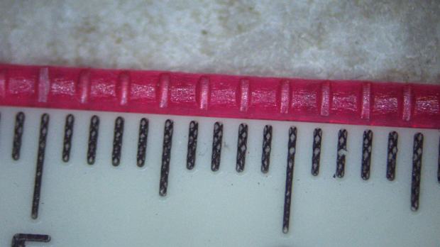
I used to think that, too, but some smarter folks straightened me out. The plastic mashes out to the sides between the drive gear teeth, so the effective drive diameter remains unchanged: each tooth tip traces a (more or less) vertical path downward through the filament (as seen by the filament). The effective diameter isn't quite at the surface of the filament, but it's close and doesn't change much with the depth of engagement.
http://softsolder.com/2015/03/13/makerg ... entations/

Image


Think of it as a rack-and-pinion drive: the linear motion doesn't depend (very much) on how deeply the pinion engages the rack.

The comments to my post explain how I got it wrong:
http://softsolder.com/2013/05/07/m2-vs- ... culations/

That post also explores why I think Makergear adjusted the extruder step/mm value to make the nominal Extrusion Multiplier come out at 1.0. The Extrusion Multiplier is a first-order Finagle Constant for the effective drive gear diameter, plus many other things, so it's definitely not the free variable some folks use it as.

User avatar
Tim
Posts: 1205
Joined: Thu Apr 10, 2014 2:19 pm
Location: Poolesville, Maryland
Contact:

Re: Difference In Printed Cubes

Post by Tim » Thu Aug 06, 2015 7:27 pm

Hmmm. . . seems like a reasonable argument, but I'm not entirely convinced. For example, the comparison to a rack-and-pinion drive doesn't entirely hold up; if a gear rack is ideally located, then there is no play between the pinion and rack gears. If the rack is a bit further away, then it creates a gap, and for every gear tooth the motor has to rotate a bit more to make up that gap. By contrast, the filament is presumably completely engaging the pinion gear, whether it is lightly touching or being cut deeply.

There's the additional complicating factor that if you look up the extruder motor part number---mine is labeled (a rare thing), indicating that it is a Kysan 1040222---you will find that it is in fact a 5.2:1 ratio gearbox, not 5:1. Which results in 441.4 steps/mm. Compared to the value MakerGear put into the firmware, 441.4 / 471.5 = 0.936, which is no longer "eerily exact".

User avatar
Tim
Posts: 1205
Joined: Thu Apr 10, 2014 2:19 pm
Location: Poolesville, Maryland
Contact:

Re: Difference In Printed Cubes

Post by Tim » Thu Aug 06, 2015 7:53 pm

I would also point out that the Makergear analysis at http://makergear.wikidot.com/m2-technical-guide uses a 5.18:1 ratio for the gearbox. . . not sure why the difference between that and the 5.2:1 value indicated on the Kysan datasheet. Also, they use 10.8mm as the outer diameter of the pinion gear, while you use 12. They come up with a theoretical value of 488.55 steps/mm. They also claim that the 471.5 steps/mm value in the firmware comes from "calibration and experimentation", concluding that
This implies an effective diameter of the drive gear of ~11.19mm, which most likely comes from the filament itself offsetting the effective circumference.
Clearly every part of this equation has a considerable amount of slop in it. You've done a number of neat experiments on it, but it will take more to really nail down what the actual feed rate of filament is. Meanwhile, fudge factors it is.

desman
Posts: 35
Joined: Mon Jun 08, 2015 2:11 am

Re: Difference In Printed Cubes

Post by desman » Thu Aug 06, 2015 10:51 pm

I am enjoying the discussion. I learn by listening all the time. I do appreciate the help.

CCVirginia
Posts: 73
Joined: Thu May 28, 2015 7:31 pm

Re: Difference In Printed Cubes

Post by CCVirginia » Fri Aug 07, 2015 12:16 am

Interesting!
As for the movement of the filament, not my area of expertise at all - but I would think the movement would be largely governed by the largest radius with which it comes in contact - this would not change. Of course in theory, theory in practice are the same - but in practice they are different. It is a bit hard to say what happens as plastic is being squished and pulled. If your experiments indicate a difference, then I guess it is - but I would be surprised.

Since the extrusion multiplier is "messed with" as part of calibration, I don't know that the formula matters that much. If that is not the variable you mess with, what is?

User avatar
ednisley
Posts: 1188
Joined: Fri Apr 11, 2014 5:34 pm
Location: Halfway up the Hudson
Contact:

Re: Difference In Printed Cubes

Post by ednisley » Fri Aug 07, 2015 12:54 am

CCVirginia wrote:If that is not the variable you mess with, what is?
The Extrusion Multiplier is the only adjustable parameter in the whole stack.

On the input side, the slicer must know the filament diameter and the number of steps required to feed 1 mm of filament, from which it computes the volume of filament per step.

On the output side, it knows desired thread thickness and width, plus the nozzle speed relative to the platform. From that, it computes the required thread volume per second.

Then it divides (thread volume/sec) by (filament volume/step) to get the extruder speed in step/sec.

If we lived in the Physics 1 world (where all cows are spherical and all students ideal), you'd measure those numbers, plug them in, and it would Just Work. The Extrusion Multiplier provides Wiggle Room to compensate for all the nonlinearities and weirdnesses between the filament spool and the final object: it makes the actual extrusion width match the desired width, so that the slicer's commands match reality.

So that's why you must do an Extrusion Multiplier dance with each new process variation: it's the one number you can vary to make the answer come out right.

Now, some folks feed in bogus numbers instead of measured values or don't care about having the slicer lay down the proper amount of plastic, but ... I ain't them. [grin]

User avatar
ednisley
Posts: 1188
Joined: Fri Apr 11, 2014 5:34 pm
Location: Halfway up the Hudson
Contact:

Re: Difference In Printed Cubes

Post by ednisley » Fri Aug 07, 2015 1:06 am

Tim wrote:and for every gear tooth the motor has to rotate a bit more to make up that gap
Even a loose rack must move exactly one tooth distance as the drive gear moves one tooth, so the linear distance per revolution remains the same no matter how loose the engagement. Involute gears don't engage nicely when the pitch circles don't match up, but that's in the nature of fine tuning.

A loose rack will have terrible backlash, but that's a different subject entirely.
Kysan 1040222
Aye! I ran with what I knew at the time, which then changed:
http://softsolder.com/2014/07/31/makerg ... tus-check/

desman
Posts: 35
Joined: Mon Jun 08, 2015 2:11 am

Re: Difference In Printed Cubes

Post by desman » Fri Aug 07, 2015 1:14 am

The cube printed with the settings supplied by Makesolid.
Attachments
40mmcubeas.zip
(3.24 KiB) Downloaded 296 times
cubeb.jpg
cubeb.jpg (344.29 KiB) Viewed 9605 times
cubea.jpg
cubea.jpg (206.83 KiB) Viewed 9605 times

User avatar
Tim
Posts: 1205
Joined: Thu Apr 10, 2014 2:19 pm
Location: Poolesville, Maryland
Contact:

Re: Difference In Printed Cubes

Post by Tim » Fri Aug 07, 2015 2:09 am

ednisley wrote:The Extrusion Multiplier is the only adjustable parameter in the whole stack.
Probably still true for slic3r, but no longer true for Simplify3D, which has an additional parameter for filament diameter. I don't think anybody really understands how changing this value interacts with the extrusion multiplier. It's just another factor to complicate things. (edit: scratch that. I meant to say that S3D has an additional parameter for filament density; of course they all have to know the filament diameter. . .)
ednisley wrote:Even a loose rack must move exactly one tooth distance as the drive gear moves one tooth, so the linear distance per revolution remains the same no matter how loose the engagement. Involute gears don't engage nicely when the pitch circles don't match up, but that's in the nature of fine tuning.
Maybe I worded it badly (I usually do), but my point was that yes, the rack moves exactly one tooth distance when the drive gear moves one tooth distance, no matter how badly adjusted. I think it's the filament that doesn't. It moves a distance based on the radius of the circle measured from the middle of the filament to the pinion gear axis, which changes depending on how deeply the pinion digs into the filament. That appears to be the argument the MakerGear guys make on the page I referenced when they say that in practice the steps/mm works out right only if you assume a pinion gear radius that's more than a mm larger than measured.

But I also think, after reading all these different discussions on the topic, that there are so many variables and fudge factors sloshing around that there is probably no definitive way to tell if the effect is real without a very well-controlled experiment. And once you have the answer, it's fairly pointless anyway. There will still be a fudge factor based on the remaining unknowns. Mostly it just makes an interesting topic for discussion.

Post Reply