Odd printing artifact

General discussion topics
Toby
Posts: 330
Joined: Wed Apr 09, 2014 9:44 pm

Odd printing artifact

Post by Toby » Sun Jun 01, 2014 8:27 am

There's this artifact that's been showing up my prints lately that I don't understand. It's a regular series of indentations in an otherwise smooth wall. Here's a pic to explain it better:
dents.JPG
dents.JPG (29.37 KiB) Viewed 11649 times
The arrow points to the second one from the bottom. If you count them, there are ten, which is also the number of segments that the arcs were divided in when modeling. So that face consists of 10 quadrilaterals that get divided into 20 triangles.

The quadrilaterals aren't planar, but I don't see how that could be the cause because each triangle is planar and there's no obvious relation between the dents and the underlying triangles. The layer height on this is .25 and the extrusion width is .5. That extrusion width was an experiment, and it may be linked to the cause because the wall is very thin- about 1.6mm I think- but I still can't see why there should be small dents like that.

I've printed a lot of these lately (see viewtopic.php?f=4&t=295) and to one degree or other the dents appear in each model. But it's less in the models that curve the most.

User avatar
Tim
Posts: 1205
Joined: Thu Apr 10, 2014 2:19 pm
Location: Poolesville, Maryland
Contact:

Re: Odd printing artifact

Post by Tim » Sun Jun 01, 2014 3:39 pm

It sounds like these dents show up only in the print, and can't be seen in either the model or toolpath views?

Toby
Posts: 330
Joined: Wed Apr 09, 2014 9:44 pm

Re: Odd printing artifact

Post by Toby » Sun Jun 01, 2014 4:40 pm

Tim wrote:It sounds like these dents show up only in the print, and can't be seen in either the model or toolpath views?
That's right. But there is something suspicious in the the gcode preview. Here are close ups of the model and toolpath for it:
dentModel.JPG
dentModel.JPG (34.36 KiB) Viewed 11636 times
dentToolpath.JPG
dentToolpath.JPG (52.37 KiB) Viewed 11636 times
This probably isn't exactly the same model I showed the picture of the dents for, but they all look the same.

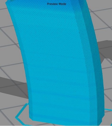
You can see the triangle structure on the models. That isn't visible in this toolpath view, but actually does show up in the finished print if you look at the right angle.

There are those bands in the toolpath that don't correspond to anything on the model. I don't know if that's related to the dents. It seems suspicious but it's not clear why it would turn into dents in the middle, rather than be a visible band like in the preview.

But looking inside the middle of the preview there is something more suspicious: gaps appear like this:
dentGCode.JPG
dentGCode.JPG (42.92 KiB) Viewed 11636 times
That must be it, so I think I just answered my own question. Though if you study the gaps closely they vary in size and location and aren't as regular as the dents in the model. My guess is that only if the gap is long enough it causes the printed model to collapse a bit for a few layers and that's the dent.

Changing the extrusion width to .4 from .5 eliminates the gaps. I'll have to print at that setting and see if it fixes it. My guess is it will.

But why those gaps appear is mysterious. The wall thickness there is 1.6 mm. It's showing three print paths, which totals 1.5mm. So there's no reason for a gap as far as I can see.

One thing worth noting: The conventional view is that S3D won't generate a toolpath if the space it has to print in is less than the extrusion width. But in this model the narrow prongs you can see in the last picture are .8 mm wide, and it always generates two paths for them even though the extrusion width is .5 mm. Being as the model has an angle to it, the actual horizontal width may be slightly larger than .8, but it's not all the way up to 1 mm. So maybe S3D will generate perimeter toolpaths even if they don't fit.

Edit: Looking even more closely, it appears the extrusion width for the prongs is different from the extrusion width for the middle path. So maybe S3D is adjusting it even though I have it manually set at .5.

And now I'm wondering exactly what is going on when it prints in the middle. IIRC from watching the prints, it ends up going back and forth 4 times, but there are only 3 lines- so it must be retracting in the middle for one length. All in all I think that .5mm extrusion width was a bad idea. I did it that way because it seemed to offer a quicker print: 3 passes to get the wall instead of 4.

jsc
Posts: 1864
Joined: Thu Apr 10, 2014 4:00 am

Re: Odd printing artifact

Post by jsc » Sun Jun 01, 2014 7:08 pm

The horizontal color bands in the gcode preview are a sign of cooling induced slowdown. The darker layers print slightly faster and so are done slightly slower.

Regarding the gap, it looks like it is happening on a straight segment, but just to be sure, is it a straight segment? Maybe you could provide your factory file?

Toby
Posts: 330
Joined: Wed Apr 09, 2014 9:44 pm

Re: Odd printing artifact

Post by Toby » Sun Jun 01, 2014 8:32 pm

jsc wrote:The horizontal color bands in the gcode preview are a sign of cooling induced slowdown. The darker layers print slightly faster and so are done slightly slower.

Regarding the gap, it looks like it is happening on a straight segment, but just to be sure, is it a straight segment? Maybe you could provide your factory file?
Ah good point about the bands. I was wondering why I only noticed them now- it's because I was printing 6 models at a time, where there was no need to slow down. But I checked the gcode with only one model, so it must have had the 10-second rule kick in.

Attached is a factory file of a normal print run with 6 models. You can see in the gcode preview that the gap appears at random places in (I think) every model, though more so in some than others.

In terms of the line being straight- actually it probably isn't, because the face is made up of 20 triangles that aren't necessarily co-planar. You can see the faint outlines of them in the picture of the model in the first post. That means that when the perimeter crosses from one triangle to another, it's not moving along the same line. That seems relevant, but why would that induce a gap in the gcode? Maybe the width drops just below a threshold on the crossing?

I just reprinted 4 of these models with the extrusion width set to .4, which is what it should have been all along before I tried to be clever. They're much better. Not only no dents, but overall cleaner in terms of surface finish and even fewer blobs. And only marginally slower than before. Here's one of them:
noDent.JPG
noDent.JPG (24.68 KiB) Viewed 11621 times
If only I hadn't just printed 40 of them at the wrong setting...
Attachments
trefoil4.7.zip
(61.1 KiB) Downloaded 371 times

User avatar
jimc
Posts: 2888
Joined: Wed Apr 09, 2014 11:30 pm
Location: mullica, nj
Contact:

Re: Odd printing artifact

Post by jimc » Mon Jun 02, 2014 1:48 am

toby that center single line is actually 2 lines they are just really close. s3d is trying to stuff that in there because it barely fits and the gaps are there because in some locations the triangles actually make the wall just a hair thinner and s3d cant stuff 2 lines in that spot. you basically have the ext width so precisely set that you are picking up these micro differences in the wall thickness. its kinda nuts actually. just put your width on auto, reslice and look at it. you wont find any gaps

jsc
Posts: 1864
Joined: Thu Apr 10, 2014 4:00 am

Re: Odd printing artifact

Post by jsc » Mon Jun 02, 2014 2:13 am

Setting it to auto just selects a width based on the height (in this case, 0.42mm), it doesn't take a look at your model and select something that will fit properly. It works in this case just because 0.42 is less than 0.5, but manually selecting 0.40 works as well.

By the way, jimc is right in that the gaps are because the wall widths are subtly changing. If you slice at 0.40 or on auto, then scroll through the gcode preview, you can see the layers dancing around just a little bit. I think you are creating your models to be 1.5 or whatever thickness, but perpendicular to the face. Combined with the twist and the lean, that means the x/y wall width diverges from your intended wall thickness.

Toby
Posts: 330
Joined: Wed Apr 09, 2014 9:44 pm

Re: Odd printing artifact

Post by Toby » Mon Jun 02, 2014 2:34 am

jsc wrote: I think you are creating your models to be 1.5 or whatever thickness, but perpendicular to the face. Combined with the twist and the lean, that means the x/y wall width diverges from your intended wall thickness.
Yes, that's right. They are 1.6 mm wide perpendicular to the face. But theoretically speaking, you can't get less than that by tilting it at an angle to the xy plane and then slicing at constant z. You can only get wider. The only thing I can't wrap my mind around is the effect of the triangulation. That could mess it up a hair, but offhand I don't think the math by itself will support the idea that the wall has become too thin .

And anyway, if S3D is actually laying down 4 paths, then at .5 they won't fit in a 1.6 mm wall. Unless now we conclude that the tilt widens the width to just right at the 2 mm level, and only occasionally falls below it due to the triangulation? But I don't believe the tilt widens it that much! I'd have to see the math to believe it.

Like Jim said, this is nuts.

I wonder if we can rig up a way to precisely measure things in the preview window. That would settle it I think. Could a magic cylinder do it?

Toby
Posts: 330
Joined: Wed Apr 09, 2014 9:44 pm

Re: Odd printing artifact

Post by Toby » Mon Jun 02, 2014 3:32 am

So here's a factory file with a model that has two prongs at exactly .8mm wide, and a connecting wall at exactly 1.6 mm wide. Perpendicular to the xy plane. I slice it with a manual extrusion width set to .5 and it fits 2 paths in the prongs and 4 paths in the connecting wall. Jim's right about the inner path being two paths that apparently overlap, but something still isn't adding up here.

Maybe it's doing a calculation based on volume, and asking, "How many paths made up of cylindrically shaped extrusions can fit inside a box shaped region of a given width and height."

No, that doesn't make sense. The width and height of the filament aren't the same, so it isn't cylindrical. Well what is the shape of the thing coming out of the nozzle anyway?
Attachments
s3dTest.zip
(2.07 KiB) Downloaded 366 times

jsc
Posts: 1864
Joined: Thu Apr 10, 2014 4:00 am

Re: Odd printing artifact

Post by jsc » Mon Jun 02, 2014 5:22 am

If you look at the gcode, the two filaments laid in the gap are .1mm apart. I think it's laying down underwidth extrusions in certain cases.

Post Reply