Extrusion calibration

Post your advice, tips, suggestions, etc...
Post Reply
jsc
Posts: 1864
Joined: Thu Apr 10, 2014 4:00 am

Extrusion calibration

Post by jsc » Sun Feb 22, 2015 7:40 pm

How to calibrate your extruder. This has come up a few times recently, so I thought I'd try it myself (I never did!) and document the process. This is all thanks to Ed Nisley's tireless efforts.

Step 0: measure your filament thickness at several points with calipers and take the average. Enter it as the filament diameter in your slicer ("Other" tab in Simplify3D).

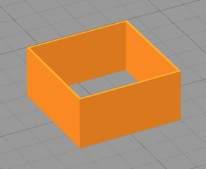
Get or create a model of a cube of the size you want. Here's a 20x20x2 model with 2mm fillets on the x/y corners.
calibration.stl.zip
(2.01 KiB) Downloaded 3810 times
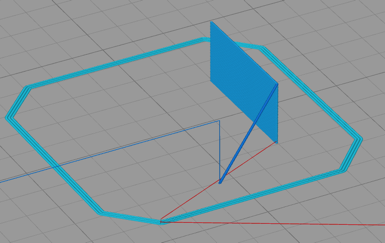
This is a solid cube; you can make your own wall-only version of whatever size using Ed's OpenSCAD model: http://softsolder.com/2014/04/18/revise ... on-object/

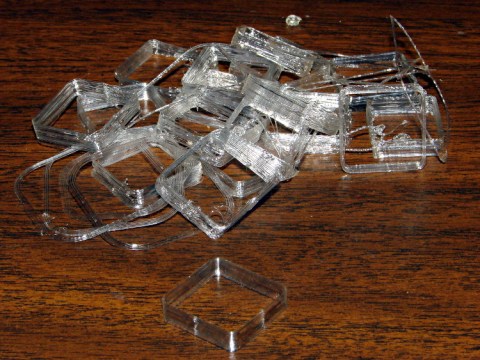
If printing the solid cube, change your settings to be single perimeter, no infill, no top or bottom layers. You will get a print like this:
extrusion-1.jpg
extrusion-1.jpg (200.2 KiB) Viewed 68619 times
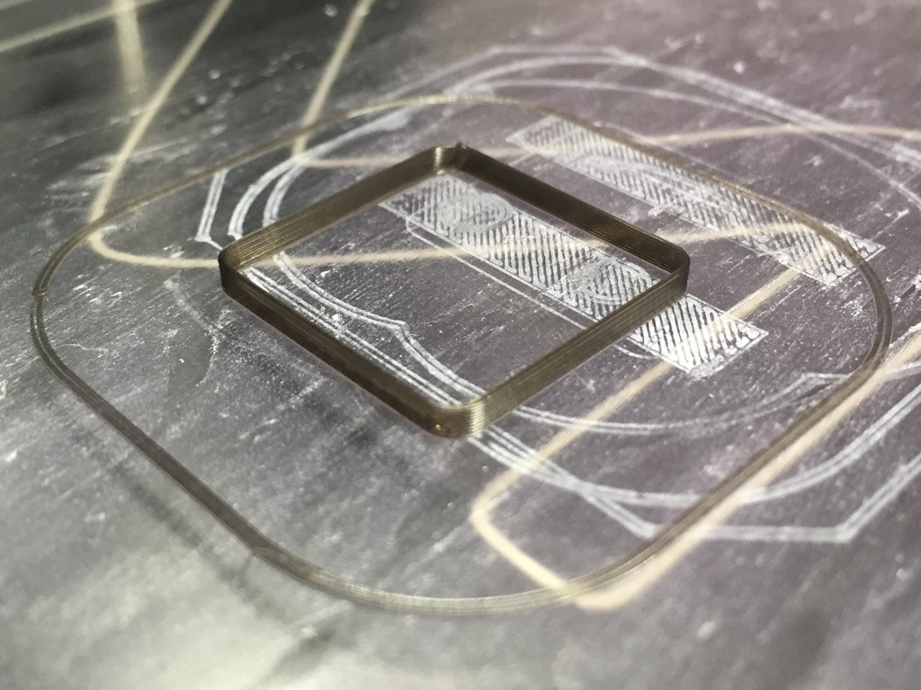
Caliper the wall at several points and eyeball the average thickness. I got measurements around 0.37mm with my current extrusion multiplier of 0.9 and extrusion width set manually to 0.40mm.
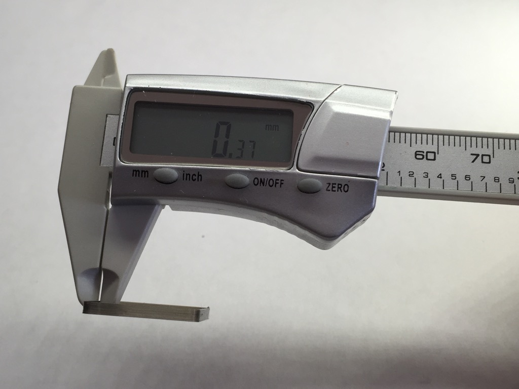
extrusion-2.jpg
extrusion-2.jpg (101.82 KiB) Viewed 68619 times
40/37 * 0.9 = .97, so I reset my extrusion multiplier to 0.97 and printed again. This time all the measurements center around 0.40 as they should:
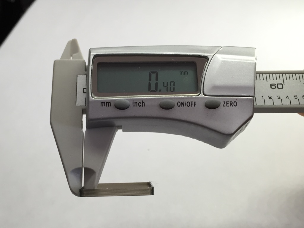
extrusion-4.jpg
extrusion-4.jpg (89.67 KiB) Viewed 68619 times
You can also take this opportunity to measure the height of the wall, which will tell you how much your z-height is off by (print using 100% first layer height):
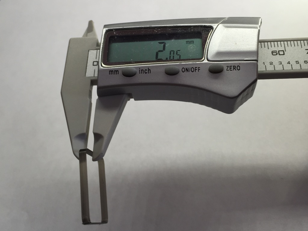
extrusion-3.jpg
extrusion-3.jpg (101.36 KiB) Viewed 68619 times
. You can fiddle with the Z end stop to fix this, but easier is to just drop the number into the G-code offset field in Simplify3D: http://www.forum.makergear.com/viewtopic.php?f=8&t=2193

A very simple exercise, everyone should try it!
Last edited by jsc on Sat Jun 06, 2015 6:31 am, edited 2 times in total.

jereywolf
Posts: 163
Joined: Fri Apr 11, 2014 9:43 pm

Re: Extrusion calibration

Post by jereywolf » Sun Feb 22, 2015 8:20 pm

I just did this today too!
My first success with printing PET+
My filament is averaging Ø.068(Ø1.73mm)
I ended with extrusion multiplier at 0.86 to get the 0.42mm extrusion width.
Attachments
10994742_781664645262961_277820025_n.jpg
10994742_781664645262961_277820025_n.jpg (51.15 KiB) Viewed 68615 times

User avatar
Jules
Posts: 3144
Joined: Wed Jan 21, 2015 1:36 am

Re: Extrusion calibration

Post by Jules » Sun Feb 22, 2015 11:31 pm

Excellent! Many thanks, and this one should be pinned for all us newbies.

Got it bookmarked, but it took a while to figure out where to go to see all the useful bookmarked topics I already had. (It's in the User Control Panel.)

User avatar
ednisley
Posts: 1188
Joined: Fri Apr 11, 2014 5:34 pm
Location: Halfway up the Hudson
Contact:

Re: Extrusion calibration

Post by ednisley » Mon Feb 23, 2015 12:47 am

jsc wrote:How to calibrate your extruder.
Excellent!

I sometimes wonder why a thinwall box isn't sticking to the platform, only to realize that I've run off half a dozen (or more!) on the exact same spot without refreshing the hair spray: they're also a good test of first-layer adhesion.

Image

That's from a writeup I did a while ago:
http://softsolder.com/2013/04/16/makerg ... st-object/

After you get the thread width and first layer height ironed out, print a solid cube with 100% infill to verify the infill settings. It should come out exactly water-level full, without overstuffing or underfilling. If not, tweak the infill width a bit.

Image

Three of those four had sparse infill that turned out to be the result of a wrecked config file:
http://softsolder.com/2014/04/21/slicin ... thin-fill/

When you get good results with both boxes, you can tackle more complex problems... and having simple, known-good objects that you can easily compare with previous results will save you days of head-scratching.

Bratag
Posts: 438
Joined: Wed Jan 14, 2015 5:33 am

Re: Extrusion calibration

Post by Bratag » Mon Feb 23, 2015 5:37 pm

This discussion leads me to a question that has always bothered me. What extrusion width should we be using. Obviously if you need a thin walled object then you go for whatever width of wall you need. But for other items whats a good rule of thumb. I generally just shoot for a width that seems to give me a gapless top layer print on a curved surface, but would be interested in a more scientific method other than ballparking it.

jsc
Posts: 1864
Joined: Thu Apr 10, 2014 4:00 am

Re: Extrusion calibration

Post by jsc » Mon Feb 23, 2015 6:14 pm

My answer is 0.40, because it is bigger than 0.35 and a round number, and therefore easy to design models around when you care about having an exact number of perimeters without gaps. You shouldn't go lower than that, and you shouldn't go higher than 0.5, because it will start to push out more plastic than the bottom of the extruder is wide. Between those, you can pick what you like, unless you start going over .2mm layer heights.

There is a concept often referred to in the reprap community as w/t, width over thickness. You want that ratio to be higher rather than lower for good adhesion, and I dimly recall the number 1.8 being thrown around as a minimum.

User avatar
ednisley
Posts: 1188
Joined: Fri Apr 11, 2014 5:34 pm
Location: Halfway up the Hudson
Contact:

Re: Extrusion calibration

Post by ednisley » Mon Feb 23, 2015 7:06 pm

Bratag wrote:a width that seems to give me a gapless top layer print
That seems like the Extrusion Multiplier isn't set quite right, because there shouldn't be any gaps, no matter what.

The Extrusion Multiplier isn't a set-and-forget constant. After you calibrate it to produce a known width, it'll be close for other widths using the same filament at similar temperatures and speeds. Vary anything too much, the extrusion process will also vary, and the new conditions call for another calibration.

Which is enough hassle that I generally chuck up a filament spool, calibrate the process to produce 0.40 mm width threads at 0.20 mm thickness, get the infill set properly, and run with that for everything until the spool runs out. Of course, I can get away with one filament and one setting because appearances don't matter much for what I'm doing and I care more about the object dimensions; some folks around here change filaments more often than I change clothes and can put up with tweaking their settings to get spectacular results.

Bratag
Posts: 438
Joined: Wed Jan 14, 2015 5:33 am

Re: Extrusion calibration

Post by Bratag » Mon Feb 23, 2015 10:18 pm

Thanks for the replies. I am a little obsessive when it comes to filament tweaks and as a rule keep a profile per color/type etc. Going to spend a little time tonight tweaking the extrusion width. Not that my printer is printing badly now (I am in love with how it prints PET+) but the quest for perfection drives me :)

User avatar
ednisley
Posts: 1188
Joined: Fri Apr 11, 2014 5:34 pm
Location: Halfway up the Hudson
Contact:

Re: Extrusion calibration

Post by ednisley » Mon Feb 23, 2015 11:07 pm

Bratag wrote:the quest for perfection drives me
You are very close to the spirit of the thing... [grin]

geddski
Posts: 14
Joined: Wed Jan 07, 2015 7:46 am

Re: Extrusion calibration

Post by geddski » Sun Mar 01, 2015 12:17 am

I'm trying to do this exercise but for some reason Simplify3d only wants to print one of the four walls (of the .4mm thin wall). Anyone know how to get it to do all four walls?

Here are my settings, based on rsilver's high quality settings:
https://dl.dropboxusercontent.com/u/309 ... ality2.fff

Image

Image

Post Reply