Visualizing 3D Printed Thread Dimensions

Post your advice, tips, suggestions, etc...
User avatar
ednisley
Posts: 1188
Joined: Fri Apr 11, 2014 5:34 pm
Location: Halfway up the Hudson
Contact:

Visualizing 3D Printed Thread Dimensions

Post by ednisley » Fri Nov 13, 2015 3:29 am

Here's what a good first layer looks like:

Image

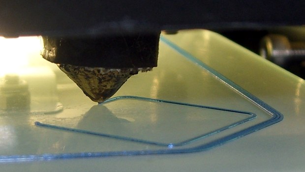
That's a 0.40 mm wide x 0.25 mm thick thread of PETG on glass, with hairspray gluing it in place.

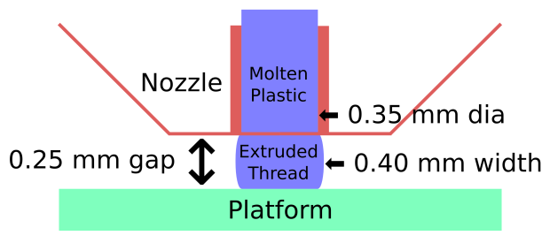
Here are the dimensions involved, more-or-less to scale:

Image

Here are some common household objects, more-or-less to the same scale:

Image

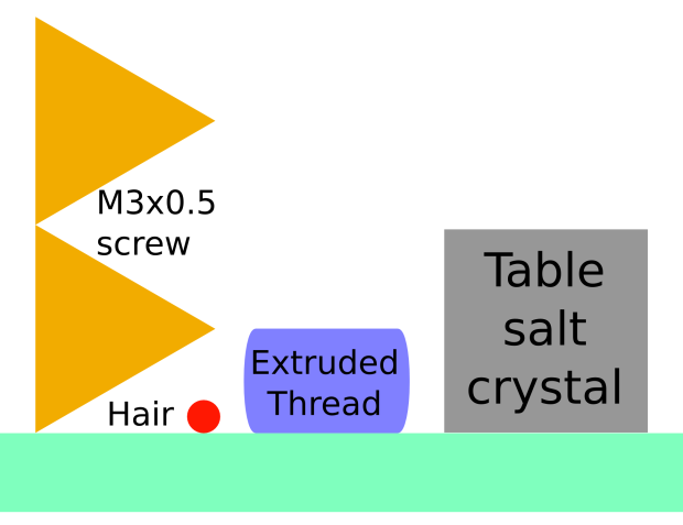
The difference between a successful first layer and junk is about twice the diameter of the hair on your head. Raising the nozzle by 0.25 mm (four hairs) means the plastic coming out of the nozzle won't even touch the platform. Lowering the nozzle by 0.25 mm means no plastic comes out of the nozzle, because it's jammed against the platform.

If you don't have the platform aligned so that the gap remains within ±0.10 mm of the nominal 0.25 mm, then the thread won't adhere properly where the gap gets large and will overfill the layer where the gap gets small.

The platform rests on three M3x0.5 mm screws. One turn of the screw moves the platform at the screw vertically by 0.50 mm. That's twice the 0.25 mm thread thickness and will move the nozzle from "jammed against the glass" to "dangling in mid air".

The edges of the platform move about twice that distance, because the platform pivots around the screws you're not turning. Call it 1 mm vertically, four times the thread thickness, at the edge.

If you turn the alignment screw by 1/6 turn, just one wrench flat, that moves the edge of the platform about 0.20 mm vertically. That's the entire difference between "too low" and "too high".

If you're trying to align the platform by eye, you're doing it wrong. You must measure the actual as-printed results and adjust based on those measurements.

Start with the Beginner's Guide so you understand what's going on:
viewtopic.php?f=8&t=2778

Use this guide to get the platform aligned close enough to work:
viewtopic.php?f=3&t=2783

Calibrate your Extrusion Multiplier to make the printed thread width match the slicer's expectations:
viewtopic.php?f=3&t=1964

Then get perfect alignment by using thinwall boxes as height gauges:
http://softsolder.com/2015/09/04/thinwa ... er-images/

When all the boxes have the proper wall thickness and height, you can print more complex objects with ease. Until then, you're probably wasting time and plastic.

Once you've set the platform correctly, you won't have to touch it again for a long time, unless you're in the habit of pulling the platform off to remove objects or bashing it with a chisel to knock objects loose. Treat the platform with respect and it'll reward you with perfect results every time...
Last edited by ednisley on Fri Nov 13, 2015 1:58 pm, edited 1 time in total.

User avatar
Jules
Posts: 3144
Joined: Wed Jan 21, 2015 1:36 am

Re: Visualizing 3D Printed Thread Dimensions

Post by Jules » Fri Nov 13, 2015 3:56 am

Sticky! :D

User avatar
SouthSideofdaSky
Posts: 103
Joined: Wed Jul 09, 2014 9:35 pm

Re: Visualizing 3D Printed Thread Dimensions

Post by SouthSideofdaSky » Fri Nov 13, 2015 1:37 pm

Thank you!

User avatar
ednisley
Posts: 1188
Joined: Fri Apr 11, 2014 5:34 pm
Location: Halfway up the Hudson
Contact:

Re: Visualizing 3D Printed Thread Dimensions

Post by ednisley » Fri Nov 13, 2015 1:59 pm

Jules wrote:Sticky! :D
Your Beginner's Guide now lives at the top of the list; sorry 'bout that.

User avatar
Jules
Posts: 3144
Joined: Wed Jan 21, 2015 1:36 am

Re: Visualizing 3D Printed Thread Dimensions

Post by Jules » Fri Nov 13, 2015 2:27 pm

ednisley wrote:
Jules wrote:Sticky! :D
Your Beginner's Guide now lives at the top of the list; sorry 'bout that.
Linked to it in the Guide as soon as I read it. :twisted: :D ;)

But the Starter's Guide is in a different Sub-Forum, this one can be stuck in the Tips/How-To section. (Who knows how many newbies even bother to read through that huge guide?) :roll:

3dPrintingMD
Posts: 277
Joined: Fri Oct 02, 2015 5:37 am

Re: Visualizing 3D Printed Thread Dimensions

Post by 3dPrintingMD » Fri Nov 13, 2015 3:20 pm

Any chance on getting the .stl that has the five boxes ? I would be like to test things out.
M2 - V4, MIC-6 Build Plate, Astrosyn Damper's(X/Y), Rev. E, Geeetech LCD

S3D - FFF Settings https://forum.simplify3d.com/viewtopic.php?f=8&t=2367
Print Quality Troubleshooting https://www.simplify3d.com/support/prin ... eshooting/

User avatar
Jules
Posts: 3144
Joined: Wed Jan 21, 2015 1:36 am

Re: Visualizing 3D Printed Thread Dimensions

Post by Jules » Fri Nov 13, 2015 4:19 pm

3dPrintingMD wrote:Any chance on getting the .stl that has the five boxes ? I would be like to test things out.
Pretty sure that's just the calibration square, duplicated 4 times and scattered around. :)

Bratag
Posts: 438
Joined: Wed Jan 14, 2015 5:33 am

Re: Visualizing 3D Printed Thread Dimensions

Post by Bratag » Fri Nov 13, 2015 5:18 pm

Jules wrote:
3dPrintingMD wrote:Any chance on getting the .stl that has the five boxes ? I would be like to test things out.
Pretty sure that's just the calibration square, duplicated 4 times and scattered around. :)
I am a fan of the circle calibration similar to http://www.thingiverse.com/thing:214621 as well.

User avatar
ednisley
Posts: 1188
Joined: Fri Apr 11, 2014 5:34 pm
Location: Halfway up the Hudson
Contact:

Re: Visualizing 3D Printed Thread Dimensions

Post by ednisley » Fri Nov 13, 2015 5:45 pm

3dPrintingMD wrote:the .stl that has the five boxes
Yup, it's just five copies of one thing, duplicated & positioned with your favorite slicer.

Being a strict constructionist, I build a model to match the slicer's width & thickness settings:
http://softsolder.com/2014/04/18/revise ... on-object/

Which, of course, requires a certain perverse taste for OpenSCAD & textual modeling. On the other paw, the model incorporates all the key dimensions and nothing else, so there's no question where any errors crept in.

You can apparently get the same result by coring out a solid box: print it with no infill & one perimeter thread.

There's a time for every style...

User avatar
ednisley
Posts: 1188
Joined: Fri Apr 11, 2014 5:34 pm
Location: Halfway up the Hudson
Contact:

Re: Visualizing 3D Printed Thread Dimensions

Post by ednisley » Fri Nov 13, 2015 5:53 pm

Bratag wrote:the circle calibration
A long time ago, on a printer far away, I did a square calibrator thing:
http://www.thingiverse.com/thing:15709

Image

Mine has the advantage you can peel it off the platform, drop it on the floor, and still figure out which way it printed: the cross tabs point to +X and +Y with the shiny side down. It also has the (dis)advantage you must/can tweak an OpenSCAD program to produce an STL matching your platform. [grin]

ABS on Kapton on machined aluminum FTW, back in the day...

Post Reply