Making a Replacement Cooling Impeller
Posted: Wed May 04, 2016 7:42 pm
One of the pieces of equipment on our lines is a large ground lug welder that clamps things like battery lugs over heavy cables between great big electrodes and zaps them with very high currents to fuse the lugs to the cable. The welding heads -- the big conductive ceramic blocks that actually contact and clamp the lugs -- are water cooled.
Yesterday this machine went down because the cooling water pump overheated. The cooling water pump overheated because the cheap plastic centrifugal impeller used to provide air cooling to the motor started to slip on the motor's shaft, at which point the hub quickly melted and the fan jammed into its housing.
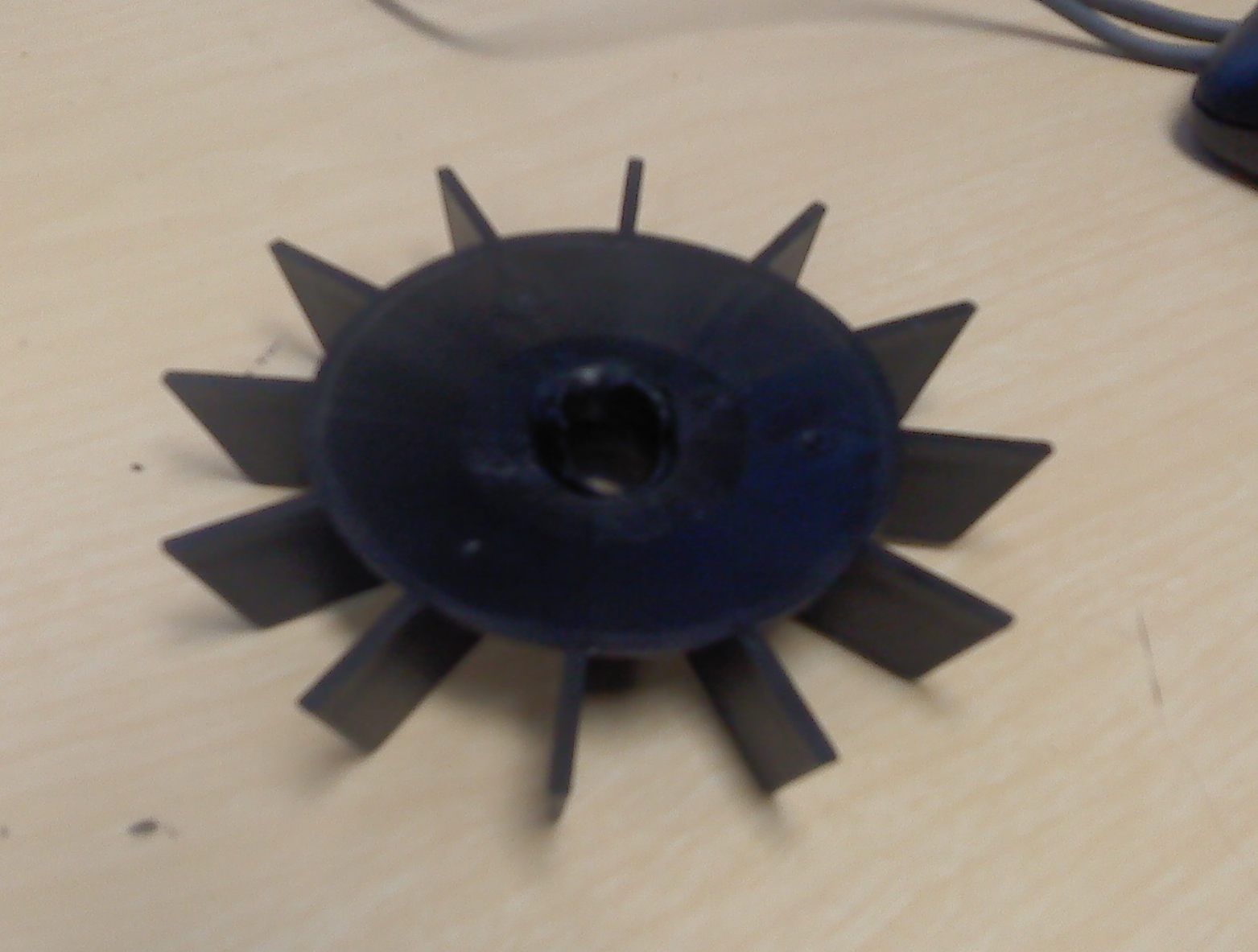
Here's the old plastic impeller:
The pump is made in Germany. The chance of getting a replacement fan quickly was nil, and getting a new pump would require modifying the enclosure and mountings for a different motor frame.
After examining the motor shaft and impeller housing, this took about 45 minutes:
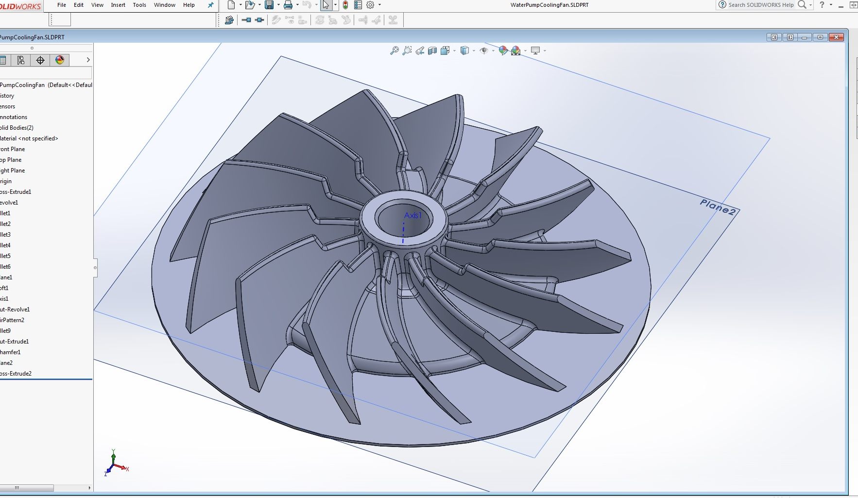
The flat disk under the impeller is a geometry raft, an adhesion platform. For precision components I always use them, sized for only upper and lower solid layers, no partial fill, and placed under the actual component. The adhesion platform adheres to the build plate and covers up any bubbles, creases, or tears on the tape, and the part is built up entirely on support laid down on the adhesion platform. I get much improved first layers topological consistency this way, no spread, no flow, no warp. I increased blade count to move more air, reduce noise, and avoid harmonics with the supply power frequency. I swept the blades back to reduce noise and to improve discharge, and I twisted the blades because the housing provides for only axial discharge as opposed to radial discharge, so my new blade is part radial impeller, part axial fan.
M2 print settings were 85% infill -- any more than that and I find I get bad distortion -- with a very small support angle limit and a very small support granularity. I run the extruder at 240 and keep the plate at 100 the whole print. Support is twenty layers at 0 degrees followed by one layer at 90, 30%, .3 mm horizontal sep, no dense layers. I find using the twenty layers at 0 and one layer at 90 support gets me very dimensionally stable non-sagging, non-warping support -- but it's still as easy to pull out as if it were purely webs at 0 degrees.
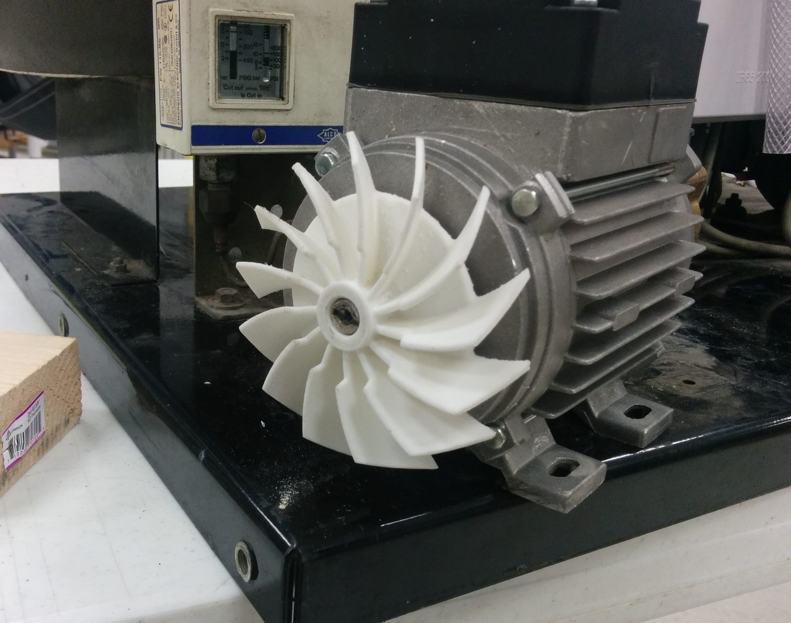
Here's the new blade assembly on the pump motor six hours later:
The pump shaft has splines intended to cut into the force-fit impeller hub, but they displace material rather than increasing the shaft diameter. I sized the bore nominal .010" smaller than the shaft diameter, which together with the standard over extrude at that diameter and density yields about a .015 total interference, so it was a nice tight fit going on with a block and mallet.
The failure occurred near an end of shift. The printer ran during plant shutdown. Installation took only a few minutes in the morning, so there was precious little actual downtime. The pump runs cooler now than it ever has, and is much quieter!
Yesterday this machine went down because the cooling water pump overheated. The cooling water pump overheated because the cheap plastic centrifugal impeller used to provide air cooling to the motor started to slip on the motor's shaft, at which point the hub quickly melted and the fan jammed into its housing.
Here's the old plastic impeller:
The pump is made in Germany. The chance of getting a replacement fan quickly was nil, and getting a new pump would require modifying the enclosure and mountings for a different motor frame.
After examining the motor shaft and impeller housing, this took about 45 minutes:
The flat disk under the impeller is a geometry raft, an adhesion platform. For precision components I always use them, sized for only upper and lower solid layers, no partial fill, and placed under the actual component. The adhesion platform adheres to the build plate and covers up any bubbles, creases, or tears on the tape, and the part is built up entirely on support laid down on the adhesion platform. I get much improved first layers topological consistency this way, no spread, no flow, no warp. I increased blade count to move more air, reduce noise, and avoid harmonics with the supply power frequency. I swept the blades back to reduce noise and to improve discharge, and I twisted the blades because the housing provides for only axial discharge as opposed to radial discharge, so my new blade is part radial impeller, part axial fan.
M2 print settings were 85% infill -- any more than that and I find I get bad distortion -- with a very small support angle limit and a very small support granularity. I run the extruder at 240 and keep the plate at 100 the whole print. Support is twenty layers at 0 degrees followed by one layer at 90, 30%, .3 mm horizontal sep, no dense layers. I find using the twenty layers at 0 and one layer at 90 support gets me very dimensionally stable non-sagging, non-warping support -- but it's still as easy to pull out as if it were purely webs at 0 degrees.
Here's the new blade assembly on the pump motor six hours later:
The pump shaft has splines intended to cut into the force-fit impeller hub, but they displace material rather than increasing the shaft diameter. I sized the bore nominal .010" smaller than the shaft diameter, which together with the standard over extrude at that diameter and density yields about a .015 total interference, so it was a nice tight fit going on with a block and mallet.
The failure occurred near an end of shift. The printer ran during plant shutdown. Installation took only a few minutes in the morning, so there was precious little actual downtime. The pump runs cooler now than it ever has, and is much quieter!