My company purchased an M2 about eight months ago for use in rapid prototyping and printing non-critical plastic parts for machines. First of all let me say that it works GREAT and we are very pleased. However as we print more and more parts, I've noticed that any circular features printed by our M2 seem to be consistently small by about 0.01"-0.03". At first I thought it was just holes, but after doing a little bit of testing it seems like external circular features are small as well - by the same amount. Visually of course, this amount of discrepancy makes no difference. But sometimes we are printing caps to fit snugly around the end of a tube, or clearance holes for bolts. With these kinds of features, 0.01"-0.03" becomes more significant.
What's odd is that it seems to be ONLY circular features that print small. Every rectangular feature the thing prints is right on size, or if there is some variation it deviates more or less randomly from the size in the model. I thought it might be something with the STL export settings in SolidWorks (which I use to make all our models), but I tried downloading and printing this test piece from Thingiverse and it was the same story - the external dimensions were right on but all the holes were too small. http://www.thingiverse.com/thing:35820
We're using Simplify3D to slice the models and run Gcode. I'm attaching a screenshot of my slicer settings. We're using black or white PLA material for the prints.
Has anyone else seen this happen? I realize we could just make the circular features slightly bigger in the model, and/or print plenty of perimeter layers and drill out the holes. But if there's some slicer setting or calibration I'm missing that is the culprit, that would obviously be a better fix. I am still not an expert by any means.
Thanks!
Printed size of circular features

Re: Printed size of circular features
This is a firmware thing. It's a known issue in the way Marlin calculates flow rates, and there's not an easy fix. The best thing to do for now is oversize the holes, or use the "adjust in XY plane" option on the last tab in S3D.
Custom 3D printing for you or your business -- quote [at] pingring.org

Re: Printed size of circular features
Yup, that gotcha has been around for as long as we've been wrapping gooey plastic around vertical cylindrical holes. Here's the great granddaddy of all posts explaining the geometric problem:SouthSideofdaSky wrote:Has anyone else seen this happen?
http://hydraraptor.blogspot.com/2011/02/polyholes.html
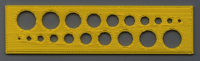
I measured a different Thingiverse test piece with uncorrected circular features:
http://softsolder.com/2013/04/21/makerg ... t-objects/

The error boiled down to a more-or-less constant 0.2-ish mm for my setup, so the fact that you're seeing 0.3 to 0.7 mm errors suggests that the actual thread width may be larger than the slicer expects. A recent discussion on Extrusion Multiplier calibration may be helpful:
viewtopic.php?f=3&t=1964
With that set up correctly, a testpiece and measurements I made with my old Thing-O-Matic may be helpful, even if the exact numbers aren't relevant:
http://softsolder.com/2011/11/25/thing- ... libration/
Replacing small cylinders with polygons, then applying a Finagle constant produces consistently good results, although I generally run a twist drill through important holes to remove the inevitable zits from the bore. I think that gives more consistent results than simply enlarging the holes, although you could probably build up a "CAD library" of standard holes for your machine.
This really isn't something that the slicer can fix on the fly, because it works from the tesselated triangles in the STL file: it doesn't know that this hole will be tapped for a screw, that hole will pass a shaft, another hole at right angles to the first two requires a flat top for good bridging, and, oh yeah, you rolled the entire model 90° around the X axis to make it fit the platform, thus the hole orientations don't match their end use. The only place all that knowledge comes together is in the CAD model, where you must design for manufacturability.
It's easier to print Stanford Bunnies, fer shure... [grin]
-
SouthSideofdaSky

- Posts: 103
- Joined: Wed Jul 09, 2014 9:35 pm
Re: Printed size of circular features
Thank you for the replies. I am sure our extruder is probably in need of calibration so that'll be my starting point. We haven't played with that area of the settings too much (just arrived at something that worked pretty well and stuck with it haha) so there's definitely room for improvement.
I may try the polygon test print as well. I'm not sure how I would efficiently apply that kind of change to our models in SolidWorks off the top of my head (we use a lot of company custom settings and stuff), but I'm sure it's possible.
I had thought of the whole "faceting error" issue with STL export, but now I see why increasing the resolution settings alone didn't seem to have much effect.
Lots of areas to think about and experiment with. Always a work in progress, of course.
Re: Printed size of circular features
It could be a simple as just adding 0.25 mm to the diameter of all holes: crude, but it fits my data pretty closely.SouthSideofdaSky wrote:efficiently apply that kind of change to our models in SolidWorks
You'll want to make your own measurements, draw your own graph, and jump to your own conclusions, of course. [grin]
That can actually work against you, because the firmware must handle a bazillion teeny tiny line segments for each hole, which can lead to stalling when the USB link pauses (which happen a lot in Windows, so I'm told). You don't gain anything after the length of a segment falls below 0.1 mm; that's roughly the mechanical resolution of the process.increasing the resolution settings
Aye, that's the spirit...Always a work in progress
-
SouthSideofdaSky
- Posts: 103
- Joined: Wed Jul 09, 2014 9:35 pm
Re: Printed size of circular features
I'm printing via SD so the USB stalling shouldn't be an issue, right? But like I said above that didn't seem to help much anyways. The 0.1 mm limit will be good to keep in mind.
And I think I'll just be oversizing the holes by some constant (possibly the 0.25 mm you suggest) in SolidWorks for now if the sizes are critical.
Thanks again!
And I think I'll just be oversizing the holes by some constant (possibly the 0.25 mm you suggest) in SolidWorks for now if the sizes are critical.
Thanks again!
Re: Printed size of circular features
That seems to be the general solution for Windows, although I've never seen a problem printing through USB from an assortment of PCs with several Ubuntu versions.SouthSideofdaSky wrote:printing via SD so the USB stalling shouldn't be an issue
Print-from-card also raises issues with PC power management that, IMO, are best solved by dedicating a box to the printer, disabling all the power management, and moving on. The smart guys seem to be using Octoprint with a Raspberry Pi strapped to the printer: a cheap solution to a number of problems.
It all boils down to managing expectations: the printing process doesn't produce the same accuracies you can take for granted with a mill or drill. Straying beyond a few mils on my Sherline would be cause for concern, but keeping within ±0.1 mm on the M2 requires sunshine, a strong tailwind, and a downhill slope...oversizing the holes by some constant
-
SouthSideofdaSky
- Posts: 103
- Joined: Wed Jul 09, 2014 9:35 pm
Re: Printed size of circular features
We're not even trying to control it at all after the print starts. I just use S3D to start the print via SD card, watch the first layer or two go down, pull the USB out to disconnect entirely from the computer, and walk away till it's done. If there's a problem I just plug the USB back in which stops the print immediately, then restart. Our M2 is plugged into a dedicated power strip so we've never had any concerns with power management.ednisley wrote:Print-from-card also raises issues with PC power management that, IMO, are best solved by dedicating a box to the printer, disabling all the power management, and moving on. The smart guys seem to be using Octoprint with a Raspberry Pi strapped to the printer: a cheap solution to a number of problems.
Ha, that's for sure!ednisley wrote:It all boils down to managing expectations: the printing process doesn't produce the same accuracies you can take for granted with a mill or drill. Straying beyond a few mils on my Sherline would be cause for concern, but keeping within ±0.1 mm on the M2 requires sunshine, a strong tailwind, and a downhill slope...