Bed Leveling not possible on my printer?
Posted: Sat Jul 11, 2015 6:45 am
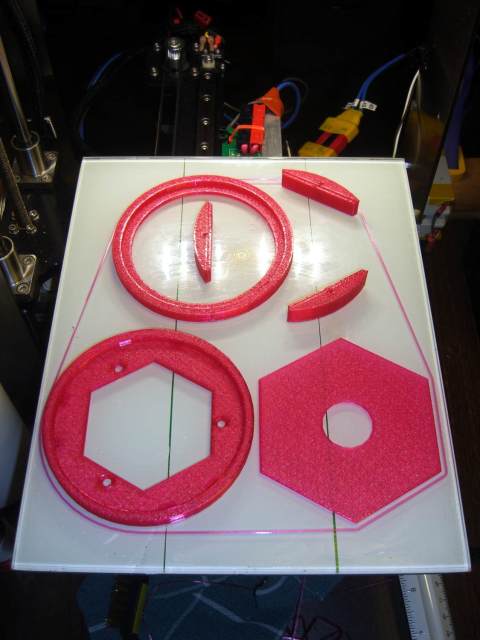
I printed up a simple dial indicator mount for the M2 Dual printer, attached a dial indicator and using the controls in Simplify3D I moved the bed around. Attached are a picture of how I placed the dial indicator and an image of the results on different points on the glass bed. I repeated this 3 or 4 times, starting at different points, moving in different directions and they all came out very similar. The result is that the dial indicator tip is tracing out a convex pattern with the high point in the center. I have dial indicator extensions, maybe another day I'll add some and repeat the measurement at different z heights to see if the z-axis is true. It's a bit late so not sure if I am missing something obvious about my dial indicator setup that could be the cause.
Likely causes:
* The left to center to right changes tells me that the x-axis rail bows down in the center since it's repeatable at all 3 x-axis measurement lines (except for the front-left corner). [This axis bowing is a major problem; short run but big changes]
* The front to center to back changes tells me that the y-axis rail bows up in the center since it's repeatable in all 3 y-axis measurement lines (except for the front-left corner). [This axis bowing is fairly minor; long run and minor changes]
* The front-left corner is odd. I had removed that paper clip from that corner but that shouldn't affect it's height; I placed the clip back for measuring purposes and it changed nothing but I haven't applied heat with the clip on. It could just be that the glass is extra thick in that corner.
Questions:
Has anyone here done a similar test with similar results?
Are the numbers I am getting typical?
Are the numbers I am getting acceptable by MakerGear standards (i.e. within expected limits)?
Print problems that will likely result (I haven't printed much yet):
On large width prints this basically means that I won't get first layer adhesion on the left and right sides when printing at .1mm layer height or even at .2mm layer height.
Solutions:
I guess I could loosen up the screws in the x-axis rail and slip some thin shims in the center then retighten the screws and see if that helps.
I know MakerGear employees read this forum, so let me know if I should send an email to tech support or if you have any recommendations.