Getting round holes on support <Solved>

Ask the MakerGear community for assistance...
User avatar
zemlin
Posts: 467
Joined: Thu Feb 04, 2016 9:32 pm
Location: Indianapolis, Indiana

Getting round holes on support <Solved>

Post by zemlin » Wed Jun 08, 2016 1:07 am

I've been dialing in my support settings for ABS builds, and I've made some good progress. The current optimum is .225mm layer, 1 layer separation top and bottom. I'm using 3 layers of dense support at 100%.
Bridging extruder multiplier 175% (might back down a touch)
Bridging speed multiplier 75% (I'm not bridging, just using these for the first layer on above the support)
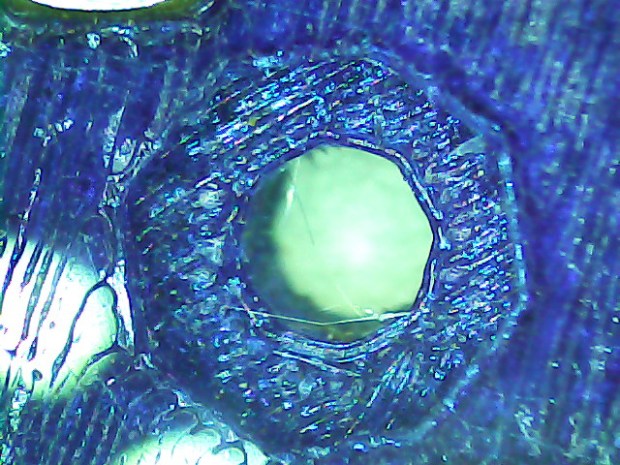
I'm getting an even, fairly dense first layer on top of the support which separates cleanly with only a bit of stress whitening - a little time in an acetone sauna would clear that up, i'm sure. The only real issue is that where I have holes starting on support, they look like this:
IMG_2114.JPG
The hole is 6mm. There's a 1mm fillet around the edge of the hole. Haven't tried a build without the fillet.
I haven't stumbled onto anything that will give me a good outline around the first holes.
Looking at some parts from Makergear, they look very clean on the underside, and circular outlines are circular.
Any tips on how to make a round hole round?

Cooling has had a fan override of 100% for bridging. Trying one now at 25%.
Last edited by zemlin on Mon Jun 20, 2016 2:11 am, edited 1 time in total.

User avatar
Matt_Sharkey
Posts: 347
Joined: Mon Oct 20, 2014 3:10 pm

Re: Getting round holes on support

Post by Matt_Sharkey » Wed Jun 08, 2016 2:04 am

Are you printing from the inside out? If the threads don't have enough to grab onto, they tend to make that pattern of the shortest path.

User avatar
zemlin
Posts: 467
Joined: Thu Feb 04, 2016 9:32 pm
Location: Indianapolis, Indiana

Re: Getting round holes on support

Post by zemlin » Wed Jun 08, 2016 3:44 am

Printing inside out.
Reduced cooling did not make the circles round.
I did make the support more difficult to break off, but not too bad.

jsc
Posts: 1864
Joined: Thu Apr 10, 2014 4:00 am

Re: Getting round holes on support

Post by jsc » Wed Jun 08, 2016 4:16 am

Holes on top of support is a problem because there is usually a single layer gap between support and the part. With that gap, tight arcs will tend to cut the corner because they don't grab onto the support before being pulled sideways.

If this is your own model, try making any such hole polygonal, at least for the interface layer.

User avatar
Jules
Posts: 3144
Joined: Wed Jan 21, 2015 1:36 am

Re: Getting round holes on support

Post by Jules » Wed Jun 08, 2016 4:32 am

Try removing that 1mm filet on the holes if you don't need it. Filets on the underside always wind up a little wonky, even with support under them. :)

User avatar
zemlin
Posts: 467
Joined: Thu Feb 04, 2016 9:32 pm
Location: Indianapolis, Indiana

Re: Getting round holes on support

Post by zemlin » Wed Jun 08, 2016 12:09 pm

I ran one last night with the bridging speed multiplier down to 10% - that didn't make any difference.
Running one with sharp corners now, although i don't expect that to be an improvement either and the 3.5mm holes at the bottom of that counterbore don't look any better without a fillet. Extruder temp is 245 which seems to be working fine for the rest of the build. I can imaging that a higher temp, less viscous material, might pull less when laying down that first layer - might try that next.

User avatar
zemlin
Posts: 467
Joined: Thu Feb 04, 2016 9:32 pm
Location: Indianapolis, Indiana

Re: Getting round holes on support

Post by zemlin » Wed Jun 08, 2016 3:31 pm

So I was able to watch it build that first layer on my current attempt and noticed that the fan when high ONLY when doing the infill - so apparently the outlines are not considered bridging and all the adjustments I've been making to extrusion multipliers and speeds haven't changed anything, which would explain why all the parts look the same in that regard - so it seems there's not much I can do to resolve the issue as I don't have any control of the outlines for the first layer - only the infill.

I guess I'll set the bridging extrusion multiplier to 100% and decrease layer thickness a bit to see if I can hit a sweet spot rather than relying on the multiplier to accomplish anything.

User avatar
Jules
Posts: 3144
Joined: Wed Jan 21, 2015 1:36 am

Re: Getting round holes on support

Post by Jules » Wed Jun 08, 2016 3:56 pm

zemlin wrote:So I was able to watch it build that first layer on my current attempt and noticed that the fan when high ONLY when doing the infill - so apparently the outlines are not considered bridging and all the adjustments I've been making to extrusion multipliers and speeds haven't changed anything, which would explain why all the parts look the same in that regard - so it seems there's not much I can do to resolve the issue as I don't have any control of the outlines for the first layer - only the infill.

I guess I'll set the bridging extrusion multiplier to 100% and decrease layer thickness a bit to see if I can hit a sweet spot rather than relying on the multiplier to accomplish anything.
On the Other tab there is a setting for Outline Underspeed - try changing that one to 50% or so. (Jin's right though - there is only so much you can do with a circular outline over a gap. Changing the Upper Vertical Separation to zero layers will improve the circle, but make it a nightmare to remove the support. :(

User avatar
zemlin
Posts: 467
Joined: Thu Feb 04, 2016 9:32 pm
Location: Indianapolis, Indiana

Re: Getting round holes on support

Post by zemlin » Wed Jun 08, 2016 4:31 pm

Jules wrote:On the Other tab there is a setting for Outline Underspeed - try changing that one to 50% or so. (Jin's right though - there is only so much you can do with a circular outline over a gap. Changing the Upper Vertical Separation to zero layers will improve the circle, but make it a nightmare to remove the support. :(
I already run the outline underspeed quite low to improve outer surface quality - and BTDT with zero layers :| I really REALLY really think the solution is for absolute dimensions as an option on separation distance rather than full layers thicknesses.
It is what it is, but I'm not defeated yet.

User avatar
ednisley
Posts: 1188
Joined: Fri Apr 11, 2014 5:34 pm
Location: Halfway up the Hudson
Contact:

Re: Getting round holes on support

Post by ednisley » Wed Jun 08, 2016 5:57 pm

zemlin wrote:absolute dimensions as an option on separation distance rather than full layers thicknesses
Because the printer builds the object from uniform slices, the separation between vertical features must be multiples of the slice thickness. You might be able to gimmick up a smaller separation by changing the layer thickess in mid-object, but that way lies madness.

For little features like that, perhaps DIY support structures would work better. Here's the inside of a hexagonal recess for a 6-32 nut, done in PETG:
https://softsolder.com/2016/02/10/vacuu ... e-sockets/

Image

The support structures pressed out cleanly:

Image

That has one empty layer between the support and the overhang. The legs on the support spiders are two threads wide and 90% of the recess diameter long.

The model shows how they fit together:

Image

I set Slic3r to produce the perimeter threads last, at a relatively slow speed, and they stick firmly to the surrounding threads.

That won't solve the problem of supporting a tapered hole, though. If that's for a flat-head screw, perhaps you can fake a taper from a two or three cylindrical steps: the edges would crush when you tighten the screw.

Post Reply