S3D Separates Rhino Model With Filleted Edges

Ask the MakerGear community for assistance...
Post Reply
CCRN
Posts: 181
Joined: Wed Jun 01, 2016 6:15 pm

S3D Separates Rhino Model With Filleted Edges

Post by CCRN » Sun Apr 23, 2017 1:25 pm

I created a very rudimentary rectangular divider in Rhino. When I exported the STL without edges filleted, S3D slices the model correctly. When I fillet the edges, something changes in the model that is causing it to separate in S3D. I decided to try Slic3r with the filleted model and the separation does not occur. This is bizarre.

Would someone mind taking a look at this? I suspect the model has errors in it, but it is rather simple, I don't understand why it would.

Here is a screenshot without the fillet..
NoFillet.png
Here is a screenshot with the fillet
Fillet.png
Links to my model and STL files on dropbox.

https://www.dropbox.com/sh/6zm0er47hxww ... RLcEa?dl=0

Thanks,
Jerold

CCRN
Posts: 181
Joined: Wed Jun 01, 2016 6:15 pm

Re: S3D Separates Rhino Model With Filleted Edges

Post by CCRN » Sun Apr 23, 2017 1:36 pm

I think I found the problem. The inner corner does not seem to join up seamlessly in Rhino. Simplify3D must not like this irregularity.
Screenshot 2017-04-23 06.34.23.png

User avatar
willnewton
Posts: 479
Joined: Wed Apr 09, 2014 8:32 pm

Re: S3D Separates Rhino Model With Filleted Edges

Post by willnewton » Sun Apr 23, 2017 3:07 pm

I don't understand why Rhino dropped such an odd break in the corner. From the way it looks, you made a square, then added a tab with a number. It is possible your planes are not aligned or that you have a naked edge at that corner.

You did do a Boolean Union on your blocks, right? Then try the "Merge all faces" command on your divider before you fillet and see if Rhino will unite your multiple part surfaces into single surfaces. If not, that is usually a good clue that you have misaligned something. I can see you have multiple surfaces, so merging faces after a Boolean when possible will serve as a good test that you are building correctly.

Rhino will spit out bad fillets when things are not put together in a way that makes it happy. Make sure to snap to your endpoints. Also, when building with lines and surfaces, use Transform>Project to Cplane to make sure your initial lines and surfaces are FLAT. Also make use of "Analyze edges" to find naked edges, which is what you may have in that corner, caused by some misalignment.

Rhino is telling you that you have built something incorrectly, but it tries really hard to make it work anyway. You have to tweak something in your design to make it right.

S3D is also telling you that you have built something incorrectly.

It is VERY SELDOM that it is the software and near 100% user error when this happens. Always go back to your design and look for errors, if the software "doesn't like" what you did, it is nearly always a case of "Garbage in=Garbage Out" as the computer tries to work with YOUR mistake.
I'm finally back to where I started two days ago!

A thread with some stuff in it I update every once in a while. viewtopic.php?f=8&t=9
See some of my stuff http://www.thingiverse.com/willnewton/favorites

User avatar
Jules
Posts: 3144
Joined: Wed Jan 21, 2015 1:36 am

Re: S3D Separates Rhino Model With Filleted Edges

Post by Jules » Sun Apr 23, 2017 9:42 pm

Also, Rhino does not always do filleted edges correctly. Known issue. (Used to drive me nuts.)

User avatar
jimc
Posts: 2888
Joined: Wed Apr 09, 2014 11:30 pm
Location: mullica, nj
Contact:

Re: S3D Separates Rhino Model With Filleted Edges

Post by jimc » Mon Apr 24, 2017 3:09 am

when you export in rhino it will warn you if the model isnt solid. there is a check box "export open object" or something like that. be sure that is not checked. filleting in rhino is finicky. it certainly works but if everything is not done just right then it will fail. in all cases there are reasons for the fail which become much less the more experience you gain with it. as jules said it can drive you nuts in the beginning.

CCRN
Posts: 181
Joined: Wed Jun 01, 2016 6:15 pm

Re: S3D Separates Rhino Model With Filleted Edges

Post by CCRN » Mon Apr 24, 2017 2:07 pm

Yep, the object was not solid. When I created the object, I extruded a large rectangle for the body and a small rectangle for the tab and joined. Drawing the divider out in 2D then extruding outline as a whole gave me proper filleting and a solid object.

User avatar
willnewton
Posts: 479
Joined: Wed Apr 09, 2014 8:32 pm

Re: S3D Separates Rhino Model With Filleted Edges

Post by willnewton » Mon Apr 24, 2017 2:33 pm

updated-Hi CCRN, I saw your new post was entered while I was working on this long explanation. I see you got it straightened out, but imma leave this here anyway. It looks like you did close to what I am suggesting in this post. Good job!
-------------

Sure Rhino can be funny with fillets, but this is a 90° meeting angle of two theoretically coplanar rectangular solids with equal height. Rhino should handle it with no issue.

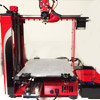
That is why I feel like this design contains planes that are either not coplanar or of equal height. The picture shows that it was built from separate forms for the body and tab. My guess is that a corner did not snap correctly. Something is not quite right about those solids.

Time to enter Expert mode:

You can just redraw the outline if they have known dimensions or if not, deconstruct the form and rebuild it from the lines as follows.

I would undo the fillets, explode the solids, delete all planes except the ones resting on the Cplane, go to TOP view, then Curve>Extract Curve from face borders, delete the surfaces, then do Transform>Project to Cplane, Explode the lines, delete the lines where the former surfaces met, draw a new line from corner to tab, Join all the lines, Create surface from Planar Curves, then, Extrude surface X amount, then Fillet edges.

Sounds like a PITA, but should take under two minutes to reverse engineer your own design and then rebuild it correctly.

Notice the steps I chose to build from the lines. I made those lines coplanar first, then made a surface from them, then extruded that surface into a solid. I did not just draw lines and Extrude planar curves or build a couple of solids to snap together, although both of those methods would work. I chose a series of steps that absolutely build the simplest, flattest solid. Each step in that series is also set up as an automatic test of the previous step.

1D-Will the lines join and are they constructed flat? The Join and Project to Cplane guarantee it.
2D-Is the surface flat? The Surface from Planar Curves command will only work if your curves are coplanar.
3D-Are your solid surfaces parallel? Extrude from Surface make sure of it.

It is not necessary to step through every dimension like that for EVERY thing you build, but when your designs start getting very complicated or you need to troubleshoot something, like this bad fillet, this is a great way to check your work. When in doubt, try to choose to generate solids from surfaces rather than lines.

At the very least you should run the Merge All Faces command often on your solids. It is a good diagnostic tool that shows you when planes that should be coplanar are not aligned. You do have to be careful that you don't merge away surface edges you may need as as reference points later.

The edges created by multiple joined surfaces can make Rhino cough up a hairball every once in a while. The best solution is to present Rhino with the simplest form possible before you fillet. It is not terribly smart at times and needs a hand.
I'm finally back to where I started two days ago!

A thread with some stuff in it I update every once in a while. viewtopic.php?f=8&t=9
See some of my stuff http://www.thingiverse.com/willnewton/favorites

CCRN
Posts: 181
Joined: Wed Jun 01, 2016 6:15 pm

Re: S3D Separates Rhino Model With Filleted Edges

Post by CCRN » Wed Apr 26, 2017 2:22 am

Hi Will Newton,

Thank you very much for taking the time to post. I really appreciate it. I cannot take credit for figuring out the proper way to design my rudimentary dividers for work. I got help from the Rhino forums. I didn't quite follow your directions when I extruded from a 2D drawing. Drawing the outline with Polyline using typed x,y coordinates vs the mouse was a learning process, so it was definitely beneficial. My steps were draw with Polyline, ExtrudeCrv, FilletEdge, TextObject for my number, then export to STL.

I finished designing 12 separate dividers today in about 45 minutes. I added Gcode to pause the print, so I can change filament color for the tab numbers. I am printing now. Being able to design your own prints is much more rewarding than printing stuff off of Thingiverse. This simple task has made me think that my wife needs a coupon box and I already can make the dividers.

Anyway, I do have some additional basic questions, but I want to run through your steps to "reverse engineer" the initial design. Hopefully I'll post back tomorrow with some followups.

Thanks again!

Jerold

User avatar
jimc
Posts: 2888
Joined: Wed Apr 09, 2014 11:30 pm
Location: mullica, nj
Contact:

Re: S3D Separates Rhino Model With Filleted Edges

Post by jimc » Wed Apr 26, 2017 2:38 am

how you did it with the polyline tool is fine. just remember to draw your design out fully in 2d first then extrude up. draw using the simplest lines or curves you can to get the desired result.

Post Reply