Think I know the answer to this one, but thought I'd get some tips/advice along the way.
I drew my first original object for printing, after some detours with a downloaded 3D Model from the internet that had a ton of 'free floating' meshes in it. S3D decided to just fill in everything inside the outlines of that object. My model imports perfectly into S3D. At least it appears exactly as it does in my CAD program. But after slicing, S3D does not want to print a number of components in my object.
So here is where I think I made my mistake, my object is composed of several 'solid' objects (aka watertight meshes), but is not one big continuous mesh. My theory is that S3D gets confused as it crosses from one solid to the next. So the solution, I believe, is to merge (weld?) my separate objects together in the CAD program, so its one single watertight mesh.
Since I'm here, suggestions on doing that are welcomed. I know of the one trick, if you can convert the model into STL format, then import the STL into the CAD program, with the setting to weld together all common mesh vertices at 180 degrees or less, should produce a single mesh, albeit, there may be holes that need to be repaired, but at least its a single graphic object.
3D Mesh Design Rules
Re: 3D Mesh Design Rules
It does not need to be continuous. Try Identify Non-manifold Edges under the repair menu to see where the problems lie. You can play around with some of the other items under Repair as well. You can also try this repair service: http://netfabb.azurewebsites.net.
If your problem is not a manifold error (and it almost certainly is), the parts that are disappearing are probably too thin to print.
If your problem is not a manifold error (and it almost certainly is), the parts that are disappearing are probably too thin to print.

Re: 3D Mesh Design Rules
I think you're confusing the term "watertight" with having several distinct objects within the same STL file.ajmadison wrote:so its one single watertight mesh
In 3D printing terms, a "watertight" model has the geometric property of being "manifold":
- All faces have the proper orientation
- Exactly two faces meet along each edge
- No faces have zero area or collinear vertices
- No faces are missing or coincident
You can certainly print multiple ("watertight" = "manifold") objects contained in the same STL file, without fusing them together:
http://softsolder.com/2014/12/04/3d-pri ... y-edition/
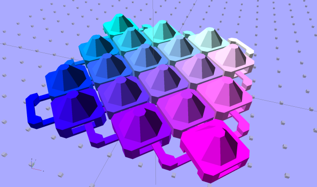
Each of those chain mail links is manifold, but they're definitely not connected. The STL file produces a single, flexible sheet with interlocking links:
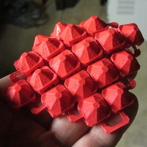
As a rule of thumb, any model created with a "3D" mesh modeling tool (Sketchup, Blender, whatever) will not be "watertight" = "manifold" and, thus, produce horrible and baffling problems when sliced. Fixing the model (or rebuilding it) to be manifold is the best solution. Attempting to get any of the mesh repair programs to fix it the way you want can produce endless frustration, but seems to be the preferred way of dealing with broken models.
Re: 3D Mesh Design Rules
Thanks, this helps for sure.
After diving back into the CAD file, I first realized that I was still drawing the wrong kind of object/s. I converted the "solids" into meshes. And yes, it helps that they're watertight, though not all of them are, but they print just fine. Though my printed object was still developing voids in it, I discovered I could not coax a couple of the meshes to "union", and because they overlapped, this caused S3D to get confused and not print around the merged area. I'm pretty sure the meshes will not merge because there are holes in the mesh in the region/s where I'm commanding boolean union. Phew, I have developed a whole new vocabulary, and I've barely gotten started.
Alas, I did not preserve any versions of the CAD file as I went from initial drawing, to solids, then converted them to meshes. I've got one (two actually) mesh that is going to be painful to rework. I had hoped this first version of the file was going to be a quick & dirty, because I planned to redraw the object with finer details. Now, I'll start from scratch and redraw the whole thing, keeping intermediate versions, in case I end up with bad (sub-component) meshes that won't union.
But I have a printed object that is mostly right. Not of interest to anyone but myself, but I'm on the right track.

Re: 3D Mesh Design Rules
Yeah, all part of the learning process. (Should have seen my first few designs in Rhino....they looked like they were all joined up properly. 
 )
)
Wait a minute....I might still have a picture of one........
Wait a minute....I might still have a picture of one........
- Spider!

Re: 3D Mesh Design Rules
Spider? Looks more like your profile pic.
____________________________________________________
See my projects at https://www.theneverendingprojectslist.com
See my projects at https://www.theneverendingprojectslist.com
Re: 3D Mesh Design Rules
That way lies madness, because the only reason those models "work" is that the slicer can compensate for whatever mesh errors it encounters.ajmadison wrote:it helps that they're watertight, though not all of them are, but they print just fine
A trivial model change can alter the mesh enough to make it un-sliceable, which inevitably starts a "But I didn't change anything!" debugging session. Been there, done that, didn't like it one little bit!
If you have an "real" 3D modeling program that manipulates 3D solids, rather than a mesh-modeling program that drapes meshes around the shape of objects (to produce lush "3D" renderings), you'll almost certainly get better results by remaining with the 3D solids as long as you possibly can. Performing CSG (Constructive Solid Geometry) operations on solids generally produces manifold results, as long as you avoid the gotchas on the list I gave earlier.converted the "solids" into meshes
The hardest lesson to learn is to not build objects by butting blocks up against each other: they must overlap very slightly to make the common faces non-coincident (they don't meet in a common plane). Better still, subtract blocks from a larger one to ensure the result remains a single solid object.
That's tedious, but seems (to me, anyhow) less annoying than repairing mesh errors ...
Re: 3D Mesh Design Rules
haha jules...its been awhile but I've seen that quite a few times before. used to get it all the time back when I first started with rhino
Re: 3D Mesh Design Rules
Actually, Ed, I think that limitation is restricted to OpenSCAD, and it is super annoying to have to add in arbitrary offsets and correct for them constantly. Every other modeler I've used allows you to butt things up together and figures out what you meant by it when you go to combine or subtract them. I vaguely remember reading a long thread about this on the mailing list, where the issue was blamed on floating point instability when truncating.ednisley wrote:The hardest lesson to learn is to not build objects by butting blocks up against each other: they must overlap very slightly to make the common faces non-coincident (they don't meet in a common plane). Better still, subtract blocks from a larger one to ensure the result remains a single solid object.
Re: 3D Mesh Design Rules
The ability to produce non-manifold geometry seems inherent in CSG modeling, although paying enough money should get you some UX improvement. It'd be interesting to build a CAD model incorporating all the "known bad" situations that produce non-manifold results, feed the ensuing STL file into a handful of mesh analysis / repair programs, iterate over all CAD programs, and tabulate the results.jsc wrote:that limitation is restricted to OpenSCAD
A dustup on the OpenSCAD mailing list about having it point out when you've screwed up the geometry seems to be resolving into "that's hard to define". Surely that's true of fancy CAD programs, where they assume they know what you meant to do and get the adjustment right nearly all the time.