Multiple processes simplify 3d
-
Deereengineer
- Posts: 21
- Joined: Mon Nov 30, 2015 9:38 pm
Multiple processes simplify 3d
I'm using 2 processes in s3d. The first is just one layer with a height of .2 mm. I want the second process to begin on the second layer. Do I set its beginning print height to .2 mm or . 4 mm since it will have the same layer height?
Re: Multiple processes simplify 3d
The first layer is at height 0, so the second one would be at height .2mm.
You should always verify that the end result looks correct after slicing by scrubbing through the g-code preview with the layer control to make sure there are no suspicious gaps.
You should always verify that the end result looks correct after slicing by scrubbing through the g-code preview with the layer control to make sure there are no suspicious gaps.
-
Deereengineer
- Posts: 21
- Joined: Mon Nov 30, 2015 9:38 pm
Re: Multiple processes simplify 3d
The first layer on the first process is of course set to zero and it is set to stop at .2mm which is the first layer height. I'm asking if the first layer of the second process should be .2 or .4mm.

Re: Multiple processes simplify 3d
jsc wrote:The first layer is at height 0, so the second one would be at height .2mm.
____________________________________________________
See my projects at https://www.theneverendingprojectslist.com
See my projects at https://www.theneverendingprojectslist.com

Re: Multiple processes simplify 3d
See, that's the thing I don't understand.jsc wrote:The first layer is at height 0, so the second one would be at height .2mm.
My setup puts Z=0 dead on the platform, so the first layer, which is 0.25 mm thick, happens at a 0.25 mm Z-axis coordinate. The second layer is at 0.50 mm and so forth and so on.
Want to do something different with a upper layer? Just figure (layer count below) x (layer thickness) and you're done.
If you want to dink with the first layer settings, then you know exactly what's going on: the coordinates in the G-Code tell you the actual Z-axis position with respect to the platform.
Bonus: measure the plastic part to see whether what happened was what you expected, with exact numeric equivalence and without any messy compensations.
Easy, simple, doesn't require any thought to figure things out. Heck, even I can understand it...
Why would you set the machine up so all the Z-axis coordinates are wrong and you have no idea where the first layer came out of the nozzle?
Yeah, I know, it's in the directions. I still don't get it ... [sigh]
-
Deereengineer
- Posts: 21
- Joined: Mon Nov 30, 2015 9:38 pm
Re: Multiple processes simplify 3d
I think I understand what you are referring to. I have done a good bit of machining and in a cnc mill we set zero to the top of the part typically ( not always). I'm new to the 3D printing but it seems odd to me that you aren't told to touch off the nozzle to the top of the build plate using a feeler then enter that number into an offset so that zero is exactly the top of the build plate.
Re: Multiple processes simplify 3d
Even with less experience than you, that's where I put the Sherline's Z=0: at the obvious position.Deereengineer wrote:done a good bit of machining
Just like that:touch off the nozzle to the top of the build plate using a feeler then enter that number into an offset so that zero is exactly the top of the build plate
https://softsolder.com/2011/02/14/thing ... er-height/

That was on the Thing-O-Matic, but the taper gauge gets me within a smidge of the right setting. Then run a thinwall square or two, measure the height, tweak the Z offset, and it's done.
But that's a whole 'nother rant... [grin]

Re: Multiple processes simplify 3d
Is that a teflon coated nozzle?ednisley wrote:
Re: Multiple processes simplify 3d
I think the confusion comes from the difference between model coordinates and machine coordinates.
The multiple process start/stop settings are all specified in model coordinates. They don't necessarily have to occur at an integer multiple of the layer height. You should set the stop height of the lower process to be exactly equal to the start height of the upper process. Anything below that height belongs to the first process, anything above to the second.
https://www.simplify3d.com/support/tuto ... f-a-model/
When you think in gcode coordinates, obviously for the first layer, the nozzle is at your first layer height, but the plastic itself begins at z=0. Coming from machining, you are probably used to thinking just about the tool head positions, but when printing the plastic has an irreducible thickness.
Re: Multiple processes simplify 3d
Maybe I'm blind to that difference, but ...jsc wrote:the difference between model coordinates and machine coordinates
In the normal case, model coordinates have Z=0 at the bottom surface of the geometry. Aligning the machine coordinates so that the mechanical Z=0 also occurs at the bottom surface of the printed plastic part seems entirely reasonable: measure 1 mm from the bottom surface and you're at the same position in both model and plastic.
With the origins matched, 1 mm above the base of the model means 1 mm above the platform: the model coordinates equal the G-Code coordinates and both of those equal the actual physical position. If you measure the plastic and it doesn't match what you see in the G-Code, it's obviously wrong.
The layer thickness depends on the slicer settings, not the model or the machine. You will use different layer thicknesses for different models, so defining the mechanical Z=0 position to be, say, one 0.25 mm layer above the platform will produce an incorrect first layer for models sliced with (say) 0.10 mm layers, unless you compensate for that mechanical setting with a first-layer slicing adjustment of some sort.the plastic itself begins at z=0
With the mechanical Z=0 position at the platform surface, changing the layer thickness doesn't require any compensation for different layer thicknesses. The nozzle simply moves to the appropriate Z-axis coordinate and poots out a plastic layer with exactly that thickness.
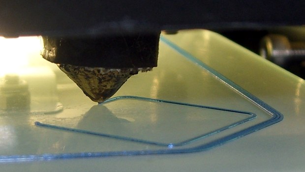
So, for example, this 0.25 mm first layer happened because that was the slicer setting:
https://softsolder.com/2015/09/04/thinw ... er-images/
I can measure that layer, compare it with the G-Code, compare it with the slicer settings, and compare it with the model: all (should) have exactly the same numeric value.
Using 0.10 mm layers requires changing one slicer setting, with no other changes. The G-Code for the first layer would contain Z0.1, rather than Z0.25, and that's what the machine would produce. Well, ideally, of course ... [grin]
With aligned coordinates, you enter exactly what you want the first layer thickness to be, without the mental gymnastics required to adjust for the mechanical offset or figure the sign of the adjustment or recall what the firmware stored for the layer thickness of a long-forgotten model.
Yes?