I printed up a simple dial indicator mount for the M2 Dual printer, attached a dial indicator and using the controls in Simplify3D I moved the bed around. Attached are a picture of how I placed the dial indicator and an image of the results on different points on the glass bed. I repeated this 3 or 4 times, starting at different points, moving in different directions and they all came out very similar. The result is that the dial indicator tip is tracing out a convex pattern with the high point in the center. I have dial indicator extensions, maybe another day I'll add some and repeat the measurement at different z heights to see if the z-axis is true. It's a bit late so not sure if I am missing something obvious about my dial indicator setup that could be the cause.
Likely causes:
* The left to center to right changes tells me that the x-axis rail bows down in the center since it's repeatable at all 3 x-axis measurement lines (except for the front-left corner). [This axis bowing is a major problem; short run but big changes]
* The front to center to back changes tells me that the y-axis rail bows up in the center since it's repeatable in all 3 y-axis measurement lines (except for the front-left corner). [This axis bowing is fairly minor; long run and minor changes]
* The front-left corner is odd. I had removed that paper clip from that corner but that shouldn't affect it's height; I placed the clip back for measuring purposes and it changed nothing but I haven't applied heat with the clip on. It could just be that the glass is extra thick in that corner.
Questions:
Has anyone here done a similar test with similar results?
Are the numbers I am getting typical?
Are the numbers I am getting acceptable by MakerGear standards (i.e. within expected limits)?
Print problems that will likely result (I haven't printed much yet):
On large width prints this basically means that I won't get first layer adhesion on the left and right sides when printing at .1mm layer height or even at .2mm layer height.
Solutions:
I guess I could loosen up the screws in the x-axis rail and slip some thin shims in the center then retighten the screws and see if that helps.
I know MakerGear employees read this forum, so let me know if I should send an email to tech support or if you have any recommendations.
Bed Leveling not possible on my printer?
Bed Leveling not possible on my printer?
- Attachments
-
- Dial indicator measurement results across the glass bed
- M2BedLevelingWDialIndicator.jpg (47.01 KiB) Viewed 15965 times
-
- dial_indicator_mounted_sm.jpg
- Dial indicator setup
- (1.19 MiB) Downloaded 210 times
Re: Bed Leveling not possible on my printer?
I am new to 3d printing and can not help you  .
.
I was wondering can you send me the file that you used to print the "dial indicator mount". I am thinking about buying same indicator and will need a mount for it.
I was wondering can you send me the file that you used to print the "dial indicator mount". I am thinking about buying same indicator and will need a mount for it.
Re: Bed Leveling not possible on my printer?
http://www.thingiverse.com/thing:918939
There you go. Just follow the directions (i.e. rotate so fan mount face is face down and add support).
There you go. Just follow the directions (i.e. rotate so fan mount face is face down and add support).
Re: Bed Leveling not possible on my printer?
I tried a dial for a while but found it more trouble than it was worth. Eyecromiter proved faster and better. Couple of things though
Always level when the bed is warm, especially with glass as it does warp.
Tighten all your leveling screws as far as they will go, then get your Z stop set correctly so that if you printed dead center the print would be fine. Then level your bed. That way you are only ever loosening screws.
Get some feeler gauges. Use them to get the distance between the hotend and various points on the bed equal distances.
Lastly - adjust Z using the S3D settings to get it perfect rather than trying to get the zstop exact.
Re: Bed Leveling not possible on my printer?
i think you will find the center of the bed to be bowed up a common thing. you need to determine if its the glass or the printer. getting an ultra flat surface can be tough. really we are talking about such a tiny amount here and i have found that if its in the x rail of the printer then it can vary with belt tension. more tension causes that to bow down. however you can make your belts too loose. adding some brass shim stock under the rail is probably not a bad idea if the x gantry of the printer is actually bowed. if its the glass then just replace the glass or switch to a mic6 build plate.
Last edited by jimc on Sun Jul 12, 2015 4:30 am, edited 1 time in total.

Re: Bed Leveling not possible on my printer?
Yup, yup, dunno... [grin]LazMech wrote:Has anyone here done a similar test with similar results?
Are the numbers I am getting typical?
Are the numbers I am getting acceptable by MakerGear standards
In round numbers, the stack of glass / heater / platform / adjustments should be flat and perpendicular to within about ±0.10 mm, but anything under that is difficult to maintain.
A year ago, an alignment ritual on my M2 took the (modified) platform alignment from ±0.5 to ±0.05:
http://softsolder.com/2014/07/16/m2-platform-leveling/
That seems to be quite stable, but I also treat the platform with exaggerated care: letting the platform cool causes the parts to pop off the hairsprayed glass without any prying and, because the (modified) platform glass is glued to the heater, it never comes off the M2.
On a stock M2, the interface between the heater and glass surfaces must be surgically clean, because a dirt particle or (shudder) hair between them will produce a bump. I wiped them clean with a low-lint cloth every time they came apart and, in general, I rarely took them apart.
The aluminum heater plate may be bent very slightly upward on the right corners; check for slight corner imperfections or burrs.
As it stands, the total range on your plate is 0.30 mm, with most of it within -0.10 of the middle. Tweak the Z offset (in your slicer) so the center is Z=+0.10, then the middle will be mashed by 0.10 and the far corners will be stretched by 0.20. That might be close enough to give good results, at least for 0.25 mm layers.
For thinner layers, tell the slicer to make the first layer 0.25 mm thick. That eliminates a huge amount of heartache and confusion: the thicker first layer soaks up all the misalignment.
Given your measurements, tighten the right-side adjusting screw by 1/12 turn (the wrench is a hexagon, so "half of a flat") to pull the right side down very slightly (0.5/12 = 0.04 mm at the screw) and re-measure the results. With a bit of luck, that will redistribute the offsets in your favor.
Use the software Z offset, rather than dinking with the mechanical Z stop screw, to make fine overall Z adjustments: you can't turn that big screw gently enough to converge on the right answer.
Because everything changes slightly when hot, I use the skirt around the parts to keep an eye on the alignment. After you set the basic alignment, the skirt thickness gives you enough information to tweak the screws without all the hassle of the dial indicator.
With a 0.25 mm layer thickness, this skirt measured 0.25±0.05 mm:
http://softsolder.com/2015/07/02/victor ... t-fixture/

Re: Bed Leveling not possible on my printer?
I will say from my experience I would say it is typical. I went to mic six plate and modified my bed springs and could not be happier. I can print multiple parts out to the extents of the build area very reliably. Belt tension does affect both bows you are talking about. If you set the belts sensibly tight and change to a mic 6 plate you can get very good results. If you are expecting lath or mill tolerances I do not think you will find it on any 3d printer. Of course this is based solely on my experience and opinion. Results may vary .
Re: Bed Leveling not possible on my printer?
Not much to add to Ed's exegesis. We've all seen doming, switching to a machined MIC6 aluminum plate has definitely reduced it, but it's still subtly there, so I think partly it comes from axis sagging and partly from bed non-flatness (but how can that be, isn't plate glass gravity leveled?) With Ed's suggested tweaks, though, it certainly is possible to fill the bed, so don't worry on that score.
You have two options: optimize for the center, or optimize for the whole bed by distributing the error. You can do this easily in the slicer with the gcode Z offset. 99% of my prints happen to occur within a few square inches of the center of the bed, so I just run my tests there. I recommend you adjust your Z offset by measuring the results of prints rather than physical extruder height if that's what's important to you (see viewtopic.php?f=3&t=1964 and links from there).
My mathematically inclined friend put together a Mathematica program to fit a plane to measured bed offsets that would tell him which way and how far to turn each bed screw. I might try to translate that into a standalone program just to see what results I can get.
Re: Bed Leveling not possible on my printer?
I wrote a really long post where I responded to everyone then I tried to attach an image and apparently I was automatically logged out and my response disappeared.
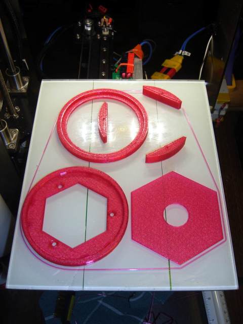
Long story short; I've leveled my bed as best I can considering the convex extruder-bed path; I'm printing a 4"x6"x3" box; the outer perimeter edges are curling/very wavy and I'm concerned that the print will fail. Attached are a picture showing the curling/wavy edges and an image of what I'm printing. I believe the edges have a 1/4" fillet. Would you guys expect such curling/waviness on the fillet overhang or is it more likely to do with the convex extruder-bed path? I could see how the convex shape would make the outer edge less well adhered which would compound to curling/waviness.
By the way ednisley (or whoever knows); do you use S3D? If so, how do you set the first layer thickness? Gotta add script? I see how to set the first layer height but that controls the squish not the thickness.
- Attachments
-
- large_print.jpg
- (331.81 KiB) Downloaded 160 times
-
- Box.jpg
- stl in S3d
- (112.98 KiB) Downloaded 160 times

Re: Bed Leveling not possible on my printer?
Couple of things - one, that design does have a rounded bottom edge - part of the curling that you are seeing is no doubt due to that filet on the bottom. Second - are you printing PLA?
It is very difficult to keep PLA from curling on overhangs, and a fileted bottom edge is a prime candidate for that curling to happen, unless you print with support of some kind. (It's very difficult to print a perfect rounded bottom edge - even with support.)
But, having said that - if you are printing PLA - hit it with as much cooling as you can. Full fan, including a desk fan if you have one, pointed directly at the curling area (which is likely happening where the fan on the machine can't reach, like that rear left corner), and you'll reduce that curling. Very important to cool PLA quickly.
That has nothing to do with the level of the bed - your print looks like it's attached as well as can be expected, on the edges that can be seen in the photo. (If you see one of the edges start to pull up away from the bed, use hairspray or gluestick to make the print stick really thoroughly to the bed. Very critical to make sure the print stays firmly attached everywhere it is supposed to while printing.)
It will probably complete the print, but you might get a bit of a messy edge or side on that uncooled area.